
Concept explainers
Videos
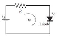
Consider the diode circuit shown in the figure. The current iD, and the voltage vDcan be determined from the solution of the following system of equations:
The system can be solved numerically or graphically. The graphical solution is found by plotting as a
Make the plots and estimate the solution for the case where I0=10-14A,
vs=1.5 V, R= 1200O, and
Want to see the full answer?
Check out a sample textbook solution
Chapter 5 Solutions
EBK MATLAB: AN INTRODUCTION WITH APPLIC


- A clipper circuit based on diodes are simple way to modify waveform in mechatronics. Assume that the two diodes shown in the circuit below are ideal diodes. If the input voltage in the circuit is a 1 kHz sinusoid with peak amplitude of 8V, sketch the Va.. (t) 10 kO 8V 10 kO Vin Vin(t) D2 Vout(t) RL Ims D1 6V -8V 4V Page | 1arrow_forwardA diode circuit is given in the below figure, in which two diodes are connected in series and their saturation currents are Is1 =10-¹6 A and Is2 =10-¹4 A. If the applied source voltage is 1 V, calculate the currents IDI and ID2 and the voltage across each diode VDI and VD2. IDI Ī Vpl + D₂ VD2arrow_forwardThe zener diode in the voltage-regulator circuit given below has a breakdown voltage of 9V. Suppose that the diode has a resistance of 1002 in the breakdown state and diode is to operate with a reverse current between 10mA and 100mA. Find the range of VS for the case that R = 2002 and RL = 6002. Is IL R + レ RL VL VS + +arrow_forward
- Consider a junction diode has dc biased current at operating point ID=0.8 mA. A sinusoidal voltage is superimposed on the VD such that the peak-to-peak sinusoidal current id(t) = 0.05ID. Find the value of the applied peak-to-peak sinusoidal voltage vd(t).arrow_forward3: Using silicon diode design a clamper that will produce output V,-20Sin wt+10 (v) when the input voltage is Vo=20Sin wt-10 (V).Draw the circuit diagram and the input and output signals. 4:The 6-V zener diode has a maximum rated power dissipated of 690 mw.Its reveres current must be at least 3mA to keep it in breakdown. Find a suitable value for Rs if V; can vary from 9v to 12v and Ri. can vary from 5000 to 1.2KO.arrow_forwardGiven the following circuit with VDD= 9.2 V, R=2.3 k2, then the current Iis: Use the CVD model for the diode, with VD = 0.65 V. I VDD a. 0.004000 A O b. 3.717391 A OC. 0 A d. 4.000000 A e. 0.003717 A R + VD -arrow_forward
- One application of the diodes is to build a clipper circuit which is used to shape the signal waveform by clipping or cutting either a portion of the positive half or negative or both halves of the signal. Write down some other Uses & Applications of the Diodes? Design a clipper circuit with positive and negative amplitudes clipped with biasing to clip the negative signal to V₁ and clip the positive signal to V₂. Where: 80 V₁ = -3 -0.01 x your last two digits of your university ID- V₂ = 2 + 0.01 x your last two digits of your university ID Design procedure: 1. Draw the schematic diagram for the circuit to be analyzed. 2. Mathematically analyze the circuit and predict the behavior of the circuit under a variety of conditions. 3. Verify the design by simulating the circuit. Carefully measure all voltages and currents, to verify the accuracy of your analysis. 4. Describe the characteristics of the circuit and how it's different in practice from the 'ideal' devices.arrow_forwardFind the voltages at V1 and V2. Consider as a practical diode. (Show Complete Solution)arrow_forwardA forward voltage of 1.75V shifts to the left at a rate 2.65mV per degree centigrade in temperature from 25°C to -35°C. What is the new forward voltage of the diode? * Your answer Find the reverse saturation current of a Silicon diode that displays a forward current of 20 mA at 0.75 V when the Thermal Voltage is 0.038 V. ( Express your answer in 3 decimal places. Your answer can be in p (pico) or n (nano) unit. e.g. only 5 nV. Upload your solution in the file upload question but type Final Answer here. * Your answerarrow_forward
- uO 9:.0 A docs.google.com * ZAIN IQ l. Q3/B: Assume an ideal diode model for all the diodes in the circuit below. calculate voltages and currents through D1 and D2 9kQ 1N1199C R2 D1 18KQ 1N1199C D3 1N1199C V2 =12 V R3 1kQ R4 5kQ 1.22 V 11 mA 0.5 A O VD1 ID1 VD2 ID2 صفحة 4 من 6arrow_forwardAs shown is a positive parallel clipper circuit which has an input voltage of E=t5V. The negative output voltage is to be -4.5V when lo is 5mA. Assume ideal diode model approximation. Determine the value of R1 in ohms. Note: Write only the numeric value of the answer, round to 4 decimal places. No need to include the unit. R, +E ww Output Input D, -E -(E-1,R,)arrow_forwardWhat voltage is boosted at the output of a multiplier.Choices: average, rms, peak, or instantaneous Which assumption is not used in the analysis of multipliers?Choices: a capacitor will not discharge, start with the cycle of the source that will forward bias the nearest diode, the output will always be multiplied, or a single diode is forward biased at a time A voltage multiplierChoices: multiplies the output voltage, has very high voltage and low current ,can employ inductors, or may not have equal numbers of diodes and capacitors A voltage regulator maintains constant voltage at the load regardless of variations atChoices: the input and output, the load, source, or in the environment Between a lower percent regulation and a higher one, which is better?Choices: lower or higherarrow_forward
 Introductory Circuit Analysis (13th Edition)Electrical EngineeringISBN:9780133923605Author:Robert L. BoylestadPublisher:PEARSON
 Delmar's Standard Textbook Of ElectricityElectrical EngineeringISBN:9781337900348Author:Stephen L. HermanPublisher:Cengage Learning
 Programmable Logic ControllersElectrical EngineeringISBN:9780073373843Author:Frank D. PetruzellaPublisher:McGraw-Hill Education
 Fundamentals of Electric CircuitsElectrical EngineeringISBN:9780078028229Author:Charles K Alexander, Matthew SadikuPublisher:McGraw-Hill Education
 Electric Circuits. (11th Edition)Electrical EngineeringISBN:9780134746968Author:James W. Nilsson, Susan RiedelPublisher:PEARSON
 Engineering ElectromagneticsElectrical EngineeringISBN:9780078028151Author:Hayt, William H. (william Hart), Jr, BUCK, John A.Publisher:Mcgraw-hill Education,