
Videos
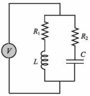
The resonant frequency f (in Hz) for the circuit shown is given by:
Given L = 0.2 H,
(a) f versus R2for
(b) f versus
Plot both plots m a single page (two plots in a column).

Trending nowThis is a popular solution!

Chapter 5 Solutions
EBK MATLAB: AN INTRODUCTION WITH APPLIC


- Determine the frequency response function, H(w), for the following circuit. What are the circuit's gain and phase at 200 kHz? O + Vi m 100 μΗ 100 Ω R Voarrow_forwardA parallel circuit with a resistance on the inductive branch has the following parameters: R = 50, L= 0.2 mH and C = 500 pF. li the total current is 0.4 A, the resonant frequency is: 503.28 GHz 503.28 kHz 503.28 THz 503.28 MHzarrow_forwardwhat is the frequency response H(jω) = Vo/Vs for the circuit below?arrow_forward
- Given a series RLC circuit: w R Q+ + V V C If R-4 Ohms, L=1 H, C=1 F, what are the center frequency wo, low cut-off frequency wLo, and high cut-off frequency WHI? Owo=1 rad/s, WLO 0.2361 rad/s, WHI 4.2361 rad/s Owo=1rad/s, WLO 9.7823 rad/s, WHI 6.2371 rad/s wo 4 rad/s, wLO 0.6872 rad/s, wHI 4.2361 rad/s Owo 4 rad/s, wLO = 9.7823 rad/s, WHI 6..2371 rad/sarrow_forwardThe current at resonance in a series L-C-R circuit is 100μA. If the applied voltage is 2 mV at a frequency of 200 kHz, and the circuit inductance is 50µH, find the circuit resistance, and the circuit capacitance.arrow_forwardIn a series RLC circuit that is operating above the resonant frequency, the current Leads the applied voltage Lags the applied voltage Is zero Is in phase with the applied voltage The mathematical relation between impedance and admittance locus are Mirrored Reciprocally O Opposite Inversely The non-sinusoidal waves which represent a sum of infinite number of harmonic waves can affect on All-of-them Electronic Devices and Circuits Power system Communications هذا السؤال مطلوبarrow_forward
- 21) Looking at the following circuit, select the correct Transfer fucntion. Please recognize that the answers are expressed in rectangular coordinates and not in magnitude, making this an easy problem. 21). ww w For the circuit in the given figure, assume L = 0.5 H and R= 200 kohm. ele O Vout (jw) Vin (jw) 200 k Vin R Vout –200 k+jw0.5 Vout (jw) ju0.5 200 k- jw0.5 Vin (jw) O Vout (ju) Vin (jw) - jw0.5 200 k– jw0.5 Vout (jw) 200 k Vin (jw) 200 k+jw0.5arrow_forward1%A. l. N O A:IA In a series RLC circuit that is operating above the resonant frequency, the current O Leads the applied voltage Is in phase with the applied voltage Lags the applied voltage Is zero The mathematical relation between impedance and admittance locus are Reciprocally Opposite Mirrored Inverselyarrow_forwardWhat is the resonant frequency of a circuit when L of 25 microhenrys and C of 10 picofarads are in parallel? * A. 10.1 kHz B. 10.1 MHz C. 101 MHz D. 101 kHzarrow_forward
- A series RLC circuit is connected to an AC power source. As shown in the figure R= 100 2, C= 80 nF, and L = 45 mH. The estimated natural resonant frequency for the circuit is R = 100 N C = 80 nF L = 45 mH O 7.5 x 10' Hz. 6.9 x 10² Hz. O 2.6 x 10° Hz. O none of the above. 1.2 x 10° Hz. 4.8 x 10° Hz. 3.5 x 10° Hz.arrow_forwardAvariable capacitance diode with Cjo = 39pF and Φj = 0.80 V is used to tune a resonant LC circuit as shown. The impedance of the RFC (radio frequency choke) can be considered infinite. What are the resonant frequencies ( fo = 1 / 2π√LC ) for VDC =1 V and VDC =9 V?arrow_forward3. Given the series RLC circuit shown below: R = 60 L = 0.30 H C = 17 uF Vac = 24V, 50Hz R M- I L mm Vm 20 C HE Calculate the following: a. Inductive reactance, Capacitive reactance b. Impedance, Circuit current c. Phase angle, power factor d. Circuit Powers: P, Q, S e. Resonant frequency, Q and BWarrow_forward
 Introductory Circuit Analysis (13th Edition)Electrical EngineeringISBN:9780133923605Author:Robert L. BoylestadPublisher:PEARSON
 Delmar's Standard Textbook Of ElectricityElectrical EngineeringISBN:9781337900348Author:Stephen L. HermanPublisher:Cengage Learning
 Programmable Logic ControllersElectrical EngineeringISBN:9780073373843Author:Frank D. PetruzellaPublisher:McGraw-Hill Education
 Fundamentals of Electric CircuitsElectrical EngineeringISBN:9780078028229Author:Charles K Alexander, Matthew SadikuPublisher:McGraw-Hill Education
 Electric Circuits. (11th Edition)Electrical EngineeringISBN:9780134746968Author:James W. Nilsson, Susan RiedelPublisher:PEARSON
 Engineering ElectromagneticsElectrical EngineeringISBN:9780078028151Author:Hayt, William H. (william Hart), Jr, BUCK, John A.Publisher:Mcgraw-hill Education,