
Loose Leaf for Engineering Circuit Analysis Format: Loose-leaf
9th Edition
ISBN: 9781259989452
Author: Hayt
Publisher: Mcgraw Hill Publishers
expand_more
expand_more
format_list_bulleted
Videos
Textbook Question
thumb_up100%
Chapter 6, Problem 21E
Referring to Fig. 6.49, sketch vout as a function of (a) vin over the range of −2 V ≤ vin ≤ +2 V, if R4 = 2 kΩ; (b) R4 over the range of 1 kΩ ≤ R4 ≤ 10 kΩ, if vin = 300 mV.
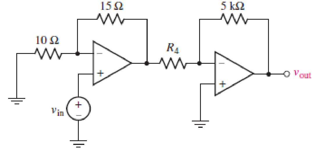
■ FIGURE 6.49
Expert Solution & Answer
Want to see the full answer?
Check out a sample textbook solution
Students have asked these similar questions
Two capacitors, of capacitance 3µF and 5µF, are connected as shown to batteries A and B which have EMF 4 V and 12 V respectively.
What is the energy stored in each of the capacitors? Calculate also the stored energy in each capacitor
when the terminals of battery A are reversed, and
when the battery B is disconnected, and the points X and Y are connected together.
A 100-pF capacitor is constructed of parallel plates of metal, each having a width W anda length L. The plates are separated by air with a distance d. Assume that L and W are bothmuch larger than d. What is the new capacitance ifa. both L and W are doubled and the other parameters are unchanged?b. the separation d is doubled and the other parameters are unchanged from their initialvalues? c. the air dielectric is replaced with oil having a relative dielectric constant of 25 and theother parameters are unchanged from their initial values ?
6
A capacitor is constructed with parallel metal plates, If the plate separation is 2 mm and the capacitance is given to 1 nano Farads, determine the area of the parallel plates of the device.
Select one:
a.
0.12 square meters
b.
0.23 square meters
c.
0.27 square meters
d.
0.20 square meters
Chapter 6 Solutions
Loose Leaf for Engineering Circuit Analysis Format: Loose-leaf
Ch. 6.2 - Derive an expression for vout in terms of vin for...Ch. 6.2 - Prob. 2PCh. 6.3 - An historic bridge is showing signs of...Ch. 6.4 - Design a circuit that provides a 12 V output if a...Ch. 6.4 - Design a noninverting Schmitt trigger that that...Ch. 6.5 - Assuming a finite open-loop gain (A), a finite...Ch. 6.5 - Use SPICE to simulate a voltage follower using an...Ch. 6 - For the op amp circuit shown in Fig. 6.39,...Ch. 6 - FIGURE 6.39 Determine the power dissipated by a...Ch. 6 - For the circuit of Fig. 6.40, calculate vout if...
Ch. 6 - For the circuit in Fig. 6.40, find the values of...Ch. 6 - (a) Design a circuit which converts a voltage...Ch. 6 - Prob. 6ECh. 6 - For the circuit of Fig. 6.40, R1 = RL = 50 ....Ch. 6 - Prob. 8ECh. 6 - (a) Design a circuit using only a single op amp...Ch. 6 - Prob. 11ECh. 6 - Determine the output voltage v0 and the current...Ch. 6 - Prob. 13ECh. 6 - Prob. 14ECh. 6 - Prob. 15ECh. 6 - Prob. 16ECh. 6 - Consider the amplifier circuit shown in Fig. 6.46....Ch. 6 - Prob. 18ECh. 6 - Prob. 19ECh. 6 - Prob. 20ECh. 6 - Referring to Fig. 6.49, sketch vout as a function...Ch. 6 - Repeat Exercise 21 using a parameter sweep in...Ch. 6 - Obtain an expression for vout as labeled in the...Ch. 6 - Prob. 24ECh. 6 - Prob. 25ECh. 6 - Prob. 26ECh. 6 - Prob. 27ECh. 6 - Prob. 28ECh. 6 - Prob. 29ECh. 6 - Prob. 30ECh. 6 - Prob. 31ECh. 6 - Determine the value of Vout for the circuit in...Ch. 6 - Calculate V0 for the circuit in Fig. 6.55. FIGURE...Ch. 6 - Prob. 34ECh. 6 - The temperature alarm circuit in Fig. 6.56...Ch. 6 - Prob. 36ECh. 6 - For the circuit depicted in Fig. 6.57, sketch the...Ch. 6 - For the circuit depicted in Fig. 6.58, (a) sketch...Ch. 6 - For the circuit depicted in Fig. 6.59, sketch the...Ch. 6 - In digital logic applications, a +5 V signal...Ch. 6 - Using the temperature sensor in the circuit in...Ch. 6 - Examine the comparator Schmitt trigger circuit in...Ch. 6 - Design the circuit values for the single supply...Ch. 6 - For the instrumentation amplifier shown in Fig....Ch. 6 - A common application for instrumentation...Ch. 6 - (a) Employ the parameters listed in Table 6.3 for...Ch. 6 - Prob. 49ECh. 6 - For the circuit of Fig. 6.62, calculate the...Ch. 6 - Prob. 51ECh. 6 - FIGURE 6.63 (a) For the circuit of Fig. 6.63, if...Ch. 6 - The difference amplifier circuit in Fig. 6.32 has...Ch. 6 - Prob. 55ECh. 6 - Prob. 56ECh. 6 - Prob. 57ECh. 6 - Prob. 58ECh. 6 - Prob. 59ECh. 6 - Prob. 60ECh. 6 - A fountain outside a certain office building is...Ch. 6 - For the circuit of Fig. 6.44, let all resistor...
Knowledge Booster


Learn more about
Need a deep-dive on the concept behind this application? Look no further. Learn more about this topic, electrical-engineering and related others by exploring similar questions and additional content below.Similar questions
- Two capacitors with 2.0 F and 3.0 F capacitance, respectively, are connected in parallel and subjected to total potential difference of 100 V. Find the (a) total capacitance, (b) charge stored in each capacitor, and (c) potential difference across each capacitor.arrow_forward1. Calculate the capacitance between two parallel plates, each of which is 100 sq. Inches and 2 mm apart in air. 2. A capacitor is charged with 0.23 J of energy at a voltage of 48V. What is its capacitance? 3. A 50-uF capacitor is initially charged. Determine the initial charge of the 50-uF capacitor if the charge transferred to a 100-uF capacitor, when connected in parallel, is 200-uC.arrow_forwardThe system of using helicopters to work on live power lines is based on the principle that electrical current seeks to flow into the ground. Select one: True Falsearrow_forward
- 4. For the network shown in Fig.4:(a) Determine the mathematical expressions for the variation of the voltage across the capacitor following the closure of the switch at t = 0 on to position 1.(b) When the switch is closed on to position 2 at t = 100 ms, determine the new expression for the capacitor voltage.(c) Plot the voltage waveform for t = 0 to t = 200 ms.arrow_forwardTwo coils of inductances 4 H and 6 H are connected in parallel. If their mutual inductance is 3 H. Calculate the equivalent inductance of the combination if mutual inductance assists and if mutual inductance opposes the self-inductance respectively.arrow_forward1. Theoretically calculate the voltage across the capacitor in the circuit of Figure 1 when t = 0 s, 5 s, 10 s, 20 s, 30 s, 40 s, and 60 s, assuming that the circuit is under DC conditions when t < 0 s and the switch is opened at t = 0 s. 2. Compare the calculated voltage at t = 20 s with the experimentally measured ∆?.arrow_forward
- The terminal voltage of a 2-H inductor is v = 10(1 – t ) V. Find the current flowing through it at t = 4s and the energy stored in it at t = 4 s. Assume i(0) = 2 A.arrow_forwardA mesh collider a) is as accurate as the triangle count on the mesh b)is the variable optiom for complex meshes such as player characters c)is the only way to get headshots to work d)is faster than a box colliderarrow_forwardThe current flowing through a 10-μF capacitor having terminals labeled a and b is i ab =0.3 exp( −2000t ) Afor t≥0 Given that v ab ( 0 )=0, find an expression for v ab (t) for t≥0. Then,find the energy stored in the capacitor for t=∞..arrow_forward
- i. How can four 100 kΩ resistors be connected so that the equivalent resistance of the four equals 250 kΩ? Sketch the arrangement, describe the resistor arrangement in words, and justify your picture by calculating the equivalent resistance. ii. Repeat part i. above with four 100 F capacitors and an equivalent capacitance of 75 F.arrow_forwardA parallel plate capacitor having area 40 cm2 and plate spacing 1.0 mm is charged to potential difference 600V. Find (a) the capacitance and (b) The energy storedarrow_forwardfor the circuit represented by the figure, the two resistance values are R=0.752Ω and R2= 1.268 Ω respectively (a) obtain an expression for the energy stored in the capacitor, valid for all t>0; (b) Determine the setting time of the voltage labaled vcarrow_forward
arrow_back_ios
SEE MORE QUESTIONS
arrow_forward_ios
Recommended textbooks for you
 Introductory Circuit Analysis (13th Edition)Electrical EngineeringISBN:9780133923605Author:Robert L. BoylestadPublisher:PEARSON
 Delmar's Standard Textbook Of ElectricityElectrical EngineeringISBN:9781337900348Author:Stephen L. HermanPublisher:Cengage Learning
 Programmable Logic ControllersElectrical EngineeringISBN:9780073373843Author:Frank D. PetruzellaPublisher:McGraw-Hill Education
 Fundamentals of Electric CircuitsElectrical EngineeringISBN:9780078028229Author:Charles K Alexander, Matthew SadikuPublisher:McGraw-Hill Education
 Electric Circuits. (11th Edition)Electrical EngineeringISBN:9780134746968Author:James W. Nilsson, Susan RiedelPublisher:PEARSON
 Engineering ElectromagneticsElectrical EngineeringISBN:9780078028151Author:Hayt, William H. (william Hart), Jr, BUCK, John A.Publisher:Mcgraw-hill Education,
Introductory Circuit Analysis (13th Edition)
Electrical Engineering
ISBN:9780133923605
Author:Robert L. Boylestad
Publisher:PEARSON
Delmar's Standard Textbook Of Electricity
Electrical Engineering
ISBN:9781337900348
Author:Stephen L. Herman
Publisher:Cengage Learning
Programmable Logic Controllers
Electrical Engineering
ISBN:9780073373843
Author:Frank D. Petruzella
Publisher:McGraw-Hill Education
Fundamentals of Electric Circuits
Electrical Engineering
ISBN:9780078028229
Author:Charles K Alexander, Matthew Sadiku
Publisher:McGraw-Hill Education
Electric Circuits. (11th Edition)
Electrical Engineering
ISBN:9780134746968
Author:James W. Nilsson, Susan Riedel
Publisher:PEARSON
Engineering Electromagnetics
Electrical Engineering
ISBN:9780078028151
Author:Hayt, William H. (william Hart), Jr, BUCK, John A.
Publisher:Mcgraw-hill Education,
Inductors Explained - The basics how inductors work working principle; Author: The Engineering Mindset;https://www.youtube.com/watch?v=KSylo01n5FY;License: Standard Youtube License