
Loose Leaf for Engineering Circuit Analysis Format: Loose-leaf
9th Edition
ISBN: 9781259989452
Author: Hayt
Publisher: Mcgraw Hill Publishers
expand_more
expand_more
format_list_bulleted
Concept explainers
Videos
Textbook Question
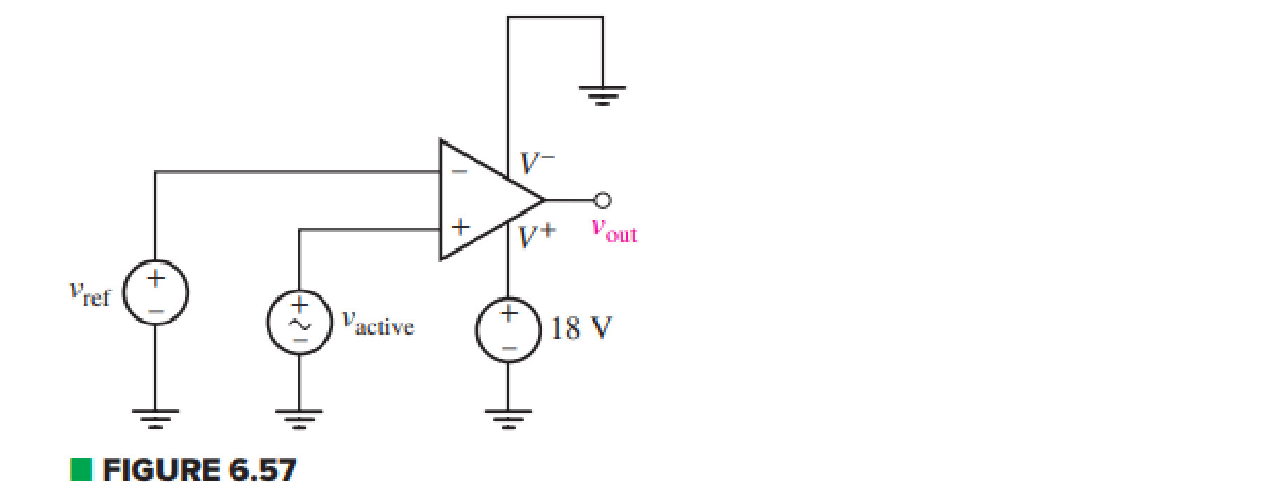
Chapter 6, Problem 37E
For the circuit depicted in Fig. 6.57, sketch the expected output voltage vout as a function of vactive for –5 V ≤ vactive ≤ +5 V, if vref is equal to (a) –3 V; (b) +3 V.
Expert Solution & Answer
Want to see the full answer?
Check out a sample textbook solution
Students have asked these similar questions
10. An equivalent model is a combination of appropriately selected circuit elements that accurately simulates the real behavior of a semiconductor device in any operating condition.
Select one:
TrueFalse
A 5 V battery, a capacitor with a capacity of 15 mkF, and a resistance of 10 kOhm are connected in series in the electrical circuit. The relaxation time in such a chain is equal to?
Design a circuit that amplifies a 500 mV signal originating from a computer keyboard, so that this signal can be interpreted by the digital circuits found on the motherboard.
Chapter 6 Solutions
Loose Leaf for Engineering Circuit Analysis Format: Loose-leaf
Ch. 6.2 - Derive an expression for vout in terms of vin for...Ch. 6.2 - Prob. 2PCh. 6.3 - An historic bridge is showing signs of...Ch. 6.4 - Design a circuit that provides a 12 V output if a...Ch. 6.4 - Design a noninverting Schmitt trigger that that...Ch. 6.5 - Assuming a finite open-loop gain (A), a finite...Ch. 6.5 - Use SPICE to simulate a voltage follower using an...Ch. 6 - For the op amp circuit shown in Fig. 6.39,...Ch. 6 - FIGURE 6.39 Determine the power dissipated by a...Ch. 6 - For the circuit of Fig. 6.40, calculate vout if...
Ch. 6 - For the circuit in Fig. 6.40, find the values of...Ch. 6 - (a) Design a circuit which converts a voltage...Ch. 6 - Prob. 6ECh. 6 - For the circuit of Fig. 6.40, R1 = RL = 50 ....Ch. 6 - Prob. 8ECh. 6 - (a) Design a circuit using only a single op amp...Ch. 6 - Prob. 11ECh. 6 - Determine the output voltage v0 and the current...Ch. 6 - Prob. 13ECh. 6 - Prob. 14ECh. 6 - Prob. 15ECh. 6 - Prob. 16ECh. 6 - Consider the amplifier circuit shown in Fig. 6.46....Ch. 6 - Prob. 18ECh. 6 - Prob. 19ECh. 6 - Prob. 20ECh. 6 - Referring to Fig. 6.49, sketch vout as a function...Ch. 6 - Repeat Exercise 21 using a parameter sweep in...Ch. 6 - Obtain an expression for vout as labeled in the...Ch. 6 - Prob. 24ECh. 6 - Prob. 25ECh. 6 - Prob. 26ECh. 6 - Prob. 27ECh. 6 - Prob. 28ECh. 6 - Prob. 29ECh. 6 - Prob. 30ECh. 6 - Prob. 31ECh. 6 - Determine the value of Vout for the circuit in...Ch. 6 - Calculate V0 for the circuit in Fig. 6.55. FIGURE...Ch. 6 - Prob. 34ECh. 6 - The temperature alarm circuit in Fig. 6.56...Ch. 6 - Prob. 36ECh. 6 - For the circuit depicted in Fig. 6.57, sketch the...Ch. 6 - For the circuit depicted in Fig. 6.58, (a) sketch...Ch. 6 - For the circuit depicted in Fig. 6.59, sketch the...Ch. 6 - In digital logic applications, a +5 V signal...Ch. 6 - Using the temperature sensor in the circuit in...Ch. 6 - Examine the comparator Schmitt trigger circuit in...Ch. 6 - Design the circuit values for the single supply...Ch. 6 - For the instrumentation amplifier shown in Fig....Ch. 6 - A common application for instrumentation...Ch. 6 - (a) Employ the parameters listed in Table 6.3 for...Ch. 6 - Prob. 49ECh. 6 - For the circuit of Fig. 6.62, calculate the...Ch. 6 - Prob. 51ECh. 6 - FIGURE 6.63 (a) For the circuit of Fig. 6.63, if...Ch. 6 - The difference amplifier circuit in Fig. 6.32 has...Ch. 6 - Prob. 55ECh. 6 - Prob. 56ECh. 6 - Prob. 57ECh. 6 - Prob. 58ECh. 6 - Prob. 59ECh. 6 - Prob. 60ECh. 6 - A fountain outside a certain office building is...Ch. 6 - For the circuit of Fig. 6.44, let all resistor...
Knowledge Booster


Learn more about
Need a deep-dive on the concept behind this application? Look no further. Learn more about this topic, electrical-engineering and related others by exploring similar questions and additional content below.Similar questions
- draw a qpsk demodulation circuit using circuit components for instance resistors, capacitors, transistors etcarrow_forwardDefibrillator machines are used to deliver an electric shock to the human heart, to resuscitate a heart that has stopped beating. It is estimated that a current as low as 18 mA through the heart is required to resuscitate. Using 95 kN as the resistance, determine the output voltage a defibrillator needs.arrow_forwardTwo coils of inductance 6 H and 8 H are connected in parallel. If their coefficient of coupling is 0.435, calculate the equivalent inductance of the combination if (a) the mutual inductance assists the self-inductance, and (ii) the mutual inductance opposes the self-inductance.arrow_forward
- Air exhibits a dielectric breakdown at fields of about 50,000 volts/in. What limitationdoes this impose on the ultimate sensitivity of a capacitance transducer such as in Fig.3arrow_forwardQI:A: Design a multi-range ammeter of 0.5 and 1 Amp. using a PMMC(galvanometer) of 500 internal resistance and full-scale current of 1 ma. Show the way of connection with the load Rarrow_forwardOne can assemble a “virtual” solar cell array by using playing cards, or business or index cards, to represent a solar cell. Combinations of these cards in series and/or parallel can model the required array output. a) Assume each card has an output of 0.5 V and a current (under bright light) of 2 A. Using your cards, how would you arrange them to produce an output of 6 A at 3 V (i.e. - 18 W)? b) Suppose you were told that you needed only 18 W (but no required voltage). Would you need more cards to make this arrangement?arrow_forward
- Design a circuit using a 200k Ohm potentiometer that has a output voltage, Vout, that ranges from a minimum of 1/3Vs volts to Vs volts.arrow_forwardCalculate the current gain A, of the amplifier circuit of Fig.6.arrow_forwardProvide an overview of "Two Externally-powered transducers".Support your answer with pictures and examplesarrow_forward
- One can assemble a “virtual” solar cell array by using playing cards, or business or index cards, to represent a solar cell. Combinations of these cards in series and/or parallel can model the required array output. Assume each card has an output of 0.5 V and a current (under bright light) of 2 A. Using your cards, how would you arrange them to produce an output of 6 A at 3 V (18 W)?Suppose you were told that you needed only 18 W (but no required voltage). Would you need more cards to make thisarrangement?arrow_forwardFor the circuit given below, let VBEQ=0.7 V, then the Q-point(VCEQ,ICEQ) equals:arrow_forwardWhere do we use SCADA in electrical engineering? Can you please explain the basic principle of it and cite some examples? Please provide answer as long as you want, I'll definitely give a like :)arrow_forward
arrow_back_ios
SEE MORE QUESTIONS
arrow_forward_ios
Recommended textbooks for you
 Introductory Circuit Analysis (13th Edition)Electrical EngineeringISBN:9780133923605Author:Robert L. BoylestadPublisher:PEARSON
 Delmar's Standard Textbook Of ElectricityElectrical EngineeringISBN:9781337900348Author:Stephen L. HermanPublisher:Cengage Learning
 Programmable Logic ControllersElectrical EngineeringISBN:9780073373843Author:Frank D. PetruzellaPublisher:McGraw-Hill Education
 Fundamentals of Electric CircuitsElectrical EngineeringISBN:9780078028229Author:Charles K Alexander, Matthew SadikuPublisher:McGraw-Hill Education
 Electric Circuits. (11th Edition)Electrical EngineeringISBN:9780134746968Author:James W. Nilsson, Susan RiedelPublisher:PEARSON
 Engineering ElectromagneticsElectrical EngineeringISBN:9780078028151Author:Hayt, William H. (william Hart), Jr, BUCK, John A.Publisher:Mcgraw-hill Education,
Introductory Circuit Analysis (13th Edition)
Electrical Engineering
ISBN:9780133923605
Author:Robert L. Boylestad
Publisher:PEARSON
Delmar's Standard Textbook Of Electricity
Electrical Engineering
ISBN:9781337900348
Author:Stephen L. Herman
Publisher:Cengage Learning
Programmable Logic Controllers
Electrical Engineering
ISBN:9780073373843
Author:Frank D. Petruzella
Publisher:McGraw-Hill Education
Fundamentals of Electric Circuits
Electrical Engineering
ISBN:9780078028229
Author:Charles K Alexander, Matthew Sadiku
Publisher:McGraw-Hill Education
Electric Circuits. (11th Edition)
Electrical Engineering
ISBN:9780134746968
Author:James W. Nilsson, Susan Riedel
Publisher:PEARSON
Engineering Electromagnetics
Electrical Engineering
ISBN:9780078028151
Author:Hayt, William H. (william Hart), Jr, BUCK, John A.
Publisher:Mcgraw-hill Education,
Current Divider Rule; Author: Neso Academy;https://www.youtube.com/watch?v=hRU1mKWUehY;License: Standard YouTube License, CC-BY