
Concept explainers
Videos
A common application for instrumentation amplifiers is to measure voltages in resistive strain gauge circuits. These strain sensors work by exploiting the changes in resistance that result from geometric distortions, as in Eq. [6] of Chap. 2. They are often part of a bridge circuit, as shown in Fig. 6.61a, where the strain gauge is identified as RG. (a) Show that
AD622 Specifications
Amplifier gain G can be varied from 2 to 1000 by connecting a resistor Between pins 1 and 8 with a value calculated by
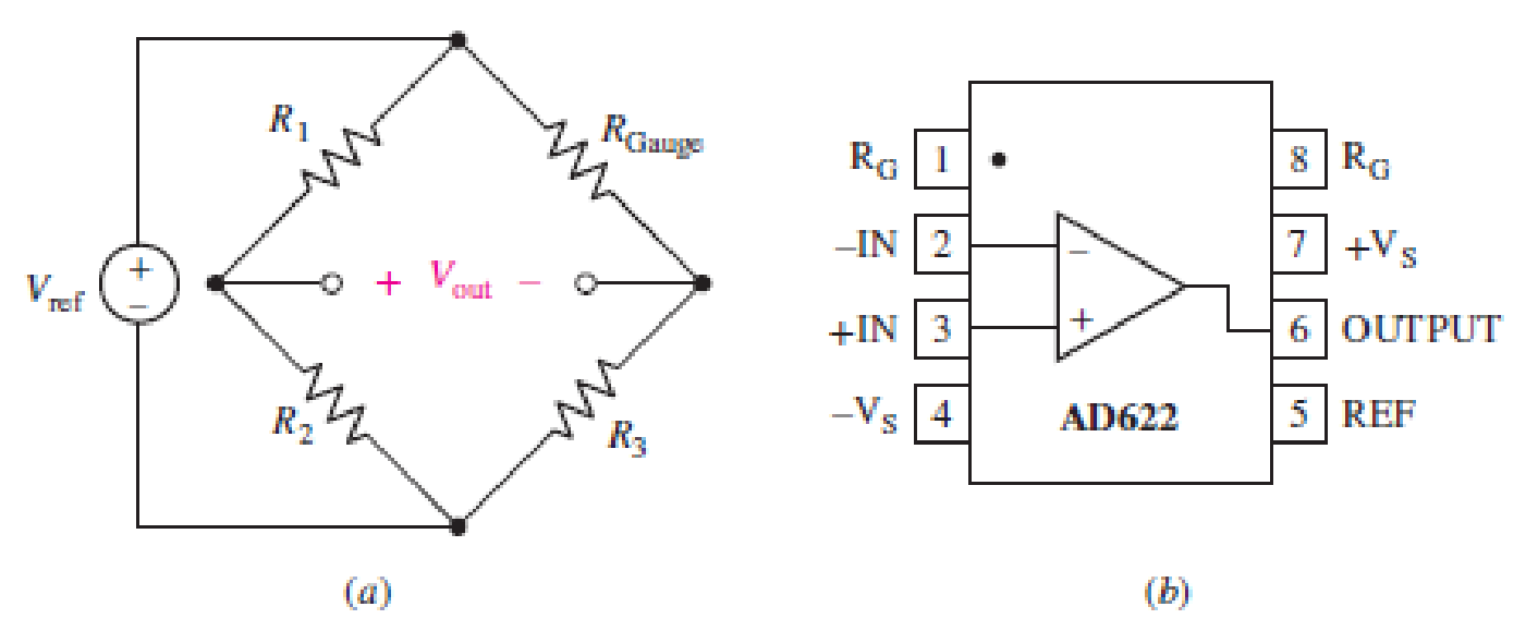
FIGURE 6.61
Want to see the full answer?
Check out a sample textbook solution
Chapter 6 Solutions
Loose Leaf for Engineering Circuit Analysis Format: Loose-leaf


- Please assist with this Matlab exercise. Image exercise 2arrow_forwardDesign a circuit that amplifies a 500 mV signal originating from a computer keyboard, so that this signal can be interpreted by the digital circuits found on the motherboard.arrow_forwardA certain microphone is capable of delivering 0.5 V when someone claps their hands at a distance of 10 ft. A particular electronic switch has a Thevenin’s equivalent resistance of 620 Ohms and requires 100 mA to energize. Using Op-Amp, design a circuit that will connect the microphone to the electronic switch in such a way that the switch is activated by someone clapping their hands. Show the details of your, including the circuit with labels. I need ASAP.arrow_forward
- What factor(s) can contribute to differences betweentheoretical (ideal) values in a circuit, and values measured inactual practice?a. Component tolerances onlyb. The sequence that components are placed in a circuitc. Measurement inaccuracy onlyd. None of the choices givene. Both component tolerances and measurement inaccuracyarrow_forwardOne can assemble a “virtual” solar cell array by using playing cards, or business or index cards, to represent a solar cell. Combinations of these cards in series and/or parallel can model the required array output. Assume each card has an output of 0.5 V and a current (under bright light) of 2 A. Using your cards, how would you arrange them to produce an output of 6 A at 3 V (18 W)?Suppose you were told that you needed only 18 W (but no required voltage). Would you need more cards to make thisarrangement?arrow_forwardA certain microphone is capable of delivering 0.5 V when someone claps their hands at a distance of 10 ft. A particular electronic switch has a Thevenin’s equivalent resistance of 620 Ohms and requires 100 mA to energize. Using Op-Amp, design a circuit that will connect the microphone to the electronic switch in such a way that the switch is activated by someone clapping their hands.arrow_forward
- One can assemble a “virtual” solar cell array by using playing cards, or business or index cards, to represent a solar cell. Combinations of these cards in series and/or parallel can model the required array output. a) Assume each card has an output of 0.5 V and a current (under bright light) of 2 A. Using your cards, how would you arrange them to produce an output of 6 A at 3 V (i.e. - 18 W)? b) Suppose you were told that you needed only 18 W (but no required voltage). Would you need more cards to make this arrangement?arrow_forwardTransform the layout of the resistor network for Q. 7 to an equivalent circuit where theresistors are at right angles, and where the network clearly shows which resistors are in series Develop a formula for the equivalent resistance of the networkarrow_forwardPlease show working out and answer for the below question. You are investigating the electrical testing circuits and find that, in an inductive circuit, the relationship between instantaneous current i (amps) and the time t (secs) is given by: i = 12.5(1-e-t/CR) Determine the time taken for current to rise from 0 to 1.9 amps with resistor value of 220 and capactor value of 0.000008arrow_forward
- (RL-Circuit). Model the RL-circuit in Fig. 66. Find a general solution when R, L, E are any constants. Graph or sketch solutions when L = 0.25H, R = 10Ω, and E = 48 V.arrow_forward8.7 MECT361 Mechatronics Components and Instrumentation 8.7. Given a 12-bit A/D converter operating over a voltage range from - 5 V to 5 V, how much does the input voltage have to change, in general, in order to be detectable? PLEASE GIVE ME THE REFRENCE I Will get zero if you didn't put the refrencearrow_forwardWhere do we use SCADA in electrical engineering? Can you please explain the basic principle of it and cite some examples? Please provide answer as long as you want, I'll definitely give a like :)arrow_forward
 Introductory Circuit Analysis (13th Edition)Electrical EngineeringISBN:9780133923605Author:Robert L. BoylestadPublisher:PEARSON
 Delmar's Standard Textbook Of ElectricityElectrical EngineeringISBN:9781337900348Author:Stephen L. HermanPublisher:Cengage Learning
 Programmable Logic ControllersElectrical EngineeringISBN:9780073373843Author:Frank D. PetruzellaPublisher:McGraw-Hill Education
 Fundamentals of Electric CircuitsElectrical EngineeringISBN:9780078028229Author:Charles K Alexander, Matthew SadikuPublisher:McGraw-Hill Education
 Electric Circuits. (11th Edition)Electrical EngineeringISBN:9780134746968Author:James W. Nilsson, Susan RiedelPublisher:PEARSON
 Engineering ElectromagneticsElectrical EngineeringISBN:9780078028151Author:Hayt, William H. (william Hart), Jr, BUCK, John A.Publisher:Mcgraw-hill Education,