
Concept explainers
Videos
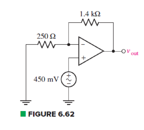
For the circuit of Fig. 6.62, calculate the differential input voltage and the input bias current if the op amp is a(n) (a) μA741; (b) LF411; (c) AD549K.
(a)
Find the differential input voltage and input bias current of op amp.
Answer to Problem 50E
The differential voltage
Explanation of Solution
Given Data:
Differential op amp is
Calculation:
The redrawn circuit of op amp is shown in Figure 1 as follows:
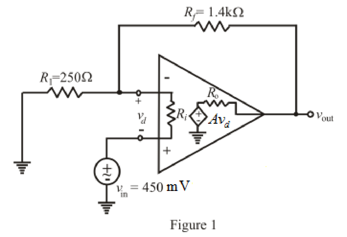
Refer to the redrawn Figure 1:
The expression for the nodal analysis at the nodal voltage
Here,
The expression for nodal analysis at nodal voltage
Here,
The expression for the bias input current of differential op amp is:
Here,
Simplify the equation (1) for
Refer to the TABLE 6.3 in the textbook.
Substitute
Rearrange for
Substitute
Substitute
Substitute
Rearrange for
Conclusion:
Thus, the differential voltage
(b)
Find the differential input voltage and input bias current of op amp.
Answer to Problem 50E
The differential voltage
Explanation of Solution
Given Data:
Differential op amp is
Calculation:
Refer to the TABLE 6.3 in the textbook.
Substitute
Rearrange for
Substitute
Substitute
Substitute
Rearrange for
Conclusion:
Thus, the differential voltage
(c)
Find the differential input voltage and input bias current of
Answer to Problem 50E
The differential voltage
Explanation of Solution
Given Data:
Differential op amp is
Calculation:
Refer to the TABLE 6.3 in the textbook.
Substitute
Rearrange for
Substitute
Substitute
Substitute
Rearrange for
Conclusion:
Thus, the differential voltage
Want to see more full solutions like this?
Chapter 6 Solutions
Loose Leaf for Engineering Circuit Analysis Format: Loose-leaf
Additional Engineering Textbook Solutions
Electric machinery fundamentals
Engineering Electromagnetics
Programmable Logic Controllers
Principles and Applications of Electrical Engineering
Fundamentals of Applied Electromagnetics (7th Edition)
Electric Circuits. (11th Edition)


- Complete the phrase! The error of a measurement system depends on the non-ideal characteristics of every element in the system. Using calibration techniques we can identify which element in the system have the most dominant non-ideal behavior. We can than devise compensation strategies for t6hese elements which should produce significant reductions in the overall system error. The methods are named .....arrow_forwardDefibrillator machines are used to deliver an electric shock to the human heart, to resuscitate a heart that has stopped beating. It is estimated that a current as low as 18 mA through the heart is required to resuscitate. Using 95 kN as the resistance, determine the output voltage a defibrillator needs.arrow_forwardIn a Ragone plot, which technology has the greatest specific energy A. Super-Capacitors B. Ni-Cd batteries C. lead acid batteries D. Li-ion batteriesarrow_forward
- One can assemble a “virtual” solar cell array by using playing cards, or business or index cards, to represent a solar cell. Combinations of these cards in series and/or parallel can model the required array output. a) Assume each card has an output of 0.5 V and a current (under bright light) of 2 A. Using your cards, how would you arrange them to produce an output of 6 A at 3 V (i.e. - 18 W)? b) Suppose you were told that you needed only 18 W (but no required voltage). Would you need more cards to make this arrangement?arrow_forwardPlease assist with this Matlab exercise. Image exercise 2arrow_forwardYou are designing a power supply for a 100 W high-quality audio amplifier that will drive an 8 Ohm speaker. The datasheet says you need approximately a 75 V Vcc rail to properly supply the transistor power stage. To get the excellent performance you expect, you aim for 1% ripple, and choose a design that minimizes the amount of capacitance required to reduce cost. Assume the diode drop is 0.7 V, and the input AC voltage available from a transformer is 75 sin(377t) V. a)How much capacitance do you need (a real-world value in μF) ? b)What is the ripple voltage at 10 W output power? c)What should be the minimum voltage rating of the capacitor(s)?arrow_forward
- draw a qpsk demodulation circuit using circuit components for instance resistors, capacitors, transistors etcarrow_forwardFind the charge stored in the 12 nF capacitor in 'mC' ?arrow_forwardAir exhibits a dielectric breakdown at fields of about 50,000 volts/in. What limitationdoes this impose on the ultimate sensitivity of a capacitance transducer such as in Fig.3arrow_forward
- A capacitor is constructed with parallel metal plates, If the plate separation is 2 mm and the capacitance is given to 1 nano Farads, determine the area of the parallel plates of the device.arrow_forwardOne can assemble a “virtual” solar cell array by using playing cards, or business or index cards, to represent a solar cell. Combinations of these cards in series and/or parallel can model the required array output. Assume each card has an output of 0.5 V and a current (under bright light) of 2 A. Using your cards, how would you arrange them to produce an output of 6 A at 3 V (18 W)?Suppose you were told that you needed only 18 W (but no required voltage). Would you need more cards to make thisarrangement?arrow_forwardCalculate the current gain A, of the amplifier circuit of Fig.6.arrow_forward
 Introductory Circuit Analysis (13th Edition)Electrical EngineeringISBN:9780133923605Author:Robert L. BoylestadPublisher:PEARSON
 Delmar's Standard Textbook Of ElectricityElectrical EngineeringISBN:9781337900348Author:Stephen L. HermanPublisher:Cengage Learning
 Programmable Logic ControllersElectrical EngineeringISBN:9780073373843Author:Frank D. PetruzellaPublisher:McGraw-Hill Education
 Fundamentals of Electric CircuitsElectrical EngineeringISBN:9780078028229Author:Charles K Alexander, Matthew SadikuPublisher:McGraw-Hill Education
 Electric Circuits. (11th Edition)Electrical EngineeringISBN:9780134746968Author:James W. Nilsson, Susan RiedelPublisher:PEARSON
 Engineering ElectromagneticsElectrical EngineeringISBN:9780078028151Author:Hayt, William H. (william Hart), Jr, BUCK, John A.Publisher:Mcgraw-hill Education,