
Loose Leaf for Engineering Circuit Analysis Format: Loose-leaf
9th Edition
ISBN: 9781259989452
Author: Hayt
Publisher: Mcgraw Hill Publishers
expand_more
expand_more
format_list_bulleted
Concept explainers
Videos
Textbook Question
Chapter 6, Problem 2E
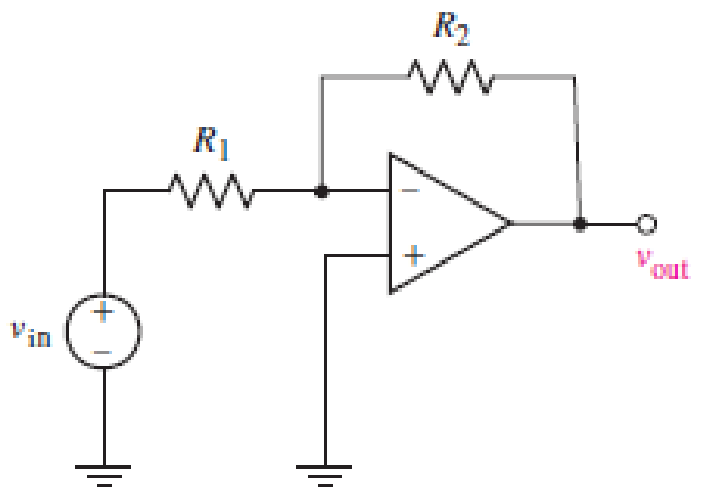
FIGURE 6.39
Determine the power dissipated by a 100 Ω resistor connected between ground and the output pin of the op amp of Fig. 6.39 if vin = 4 V and (a) R1 = 2R2; (b) R1 = 1 kΩ and R2 = 22 kΩ; (c) R1 = 100 Ω and R2 = 101 Ω.
Expert Solution & Answer
Want to see the full answer?
Check out a sample textbook solution
Students have asked these similar questions
The system of using helicopters to work on live power lines is based on the principle that electrical current seeks to flow into the ground.
Select one:
True
False
One can assemble a “virtual” solar cell array by using playing cards, or business or index cards, to represent a solar cell. Combinations of these cards in series and/or parallel can model the required array output.
a) Assume each card has an output of 0.5 V and a current (under bright light) of 2 A. Using your cards, how would you arrange them to produce an output of 6 A at 3 V (i.e. - 18 W)?
b) Suppose you were told that you needed only 18 W (but no required voltage). Would you need more cards to make this arrangement?
In a city in England with a temperature of 18 ° C, it is desired to install a wind farm with 10 wind turbines 80m high and aerodynamic coefficient equal to 0.3. For this, a study of wind measurement through an anemometer installed at 15 m height indicating speed 5 m / s in a place with high grass. Size the turbine blades in this wind farm so that obtain a mechanical power of 500 kW that will supply the entire community, calculating the diameter of the rotor blades.
Chapter 6 Solutions
Loose Leaf for Engineering Circuit Analysis Format: Loose-leaf
Ch. 6.2 - Derive an expression for vout in terms of vin for...Ch. 6.2 - Prob. 2PCh. 6.3 - An historic bridge is showing signs of...Ch. 6.4 - Design a circuit that provides a 12 V output if a...Ch. 6.4 - Design a noninverting Schmitt trigger that that...Ch. 6.5 - Assuming a finite open-loop gain (A), a finite...Ch. 6.5 - Use SPICE to simulate a voltage follower using an...Ch. 6 - For the op amp circuit shown in Fig. 6.39,...Ch. 6 - FIGURE 6.39 Determine the power dissipated by a...Ch. 6 - For the circuit of Fig. 6.40, calculate vout if...
Ch. 6 - For the circuit in Fig. 6.40, find the values of...Ch. 6 - (a) Design a circuit which converts a voltage...Ch. 6 - Prob. 6ECh. 6 - For the circuit of Fig. 6.40, R1 = RL = 50 ....Ch. 6 - Prob. 8ECh. 6 - (a) Design a circuit using only a single op amp...Ch. 6 - Prob. 11ECh. 6 - Determine the output voltage v0 and the current...Ch. 6 - Prob. 13ECh. 6 - Prob. 14ECh. 6 - Prob. 15ECh. 6 - Prob. 16ECh. 6 - Consider the amplifier circuit shown in Fig. 6.46....Ch. 6 - Prob. 18ECh. 6 - Prob. 19ECh. 6 - Prob. 20ECh. 6 - Referring to Fig. 6.49, sketch vout as a function...Ch. 6 - Repeat Exercise 21 using a parameter sweep in...Ch. 6 - Obtain an expression for vout as labeled in the...Ch. 6 - Prob. 24ECh. 6 - Prob. 25ECh. 6 - Prob. 26ECh. 6 - Prob. 27ECh. 6 - Prob. 28ECh. 6 - Prob. 29ECh. 6 - Prob. 30ECh. 6 - Prob. 31ECh. 6 - Determine the value of Vout for the circuit in...Ch. 6 - Calculate V0 for the circuit in Fig. 6.55. FIGURE...Ch. 6 - Prob. 34ECh. 6 - The temperature alarm circuit in Fig. 6.56...Ch. 6 - Prob. 36ECh. 6 - For the circuit depicted in Fig. 6.57, sketch the...Ch. 6 - For the circuit depicted in Fig. 6.58, (a) sketch...Ch. 6 - For the circuit depicted in Fig. 6.59, sketch the...Ch. 6 - In digital logic applications, a +5 V signal...Ch. 6 - Using the temperature sensor in the circuit in...Ch. 6 - Examine the comparator Schmitt trigger circuit in...Ch. 6 - Design the circuit values for the single supply...Ch. 6 - For the instrumentation amplifier shown in Fig....Ch. 6 - A common application for instrumentation...Ch. 6 - (a) Employ the parameters listed in Table 6.3 for...Ch. 6 - Prob. 49ECh. 6 - For the circuit of Fig. 6.62, calculate the...Ch. 6 - Prob. 51ECh. 6 - FIGURE 6.63 (a) For the circuit of Fig. 6.63, if...Ch. 6 - The difference amplifier circuit in Fig. 6.32 has...Ch. 6 - Prob. 55ECh. 6 - Prob. 56ECh. 6 - Prob. 57ECh. 6 - Prob. 58ECh. 6 - Prob. 59ECh. 6 - Prob. 60ECh. 6 - A fountain outside a certain office building is...Ch. 6 - For the circuit of Fig. 6.44, let all resistor...
Knowledge Booster


Learn more about
Need a deep-dive on the concept behind this application? Look no further. Learn more about this topic, electrical-engineering and related others by exploring similar questions and additional content below.Similar questions
- Design a circuit that amplifies a 500 mV signal originating from a computer keyboard, so that this signal can be interpreted by the digital circuits found on the motherboard.arrow_forwardDesign a solar PV panel that can deliver 400W at 38V from a cross-sectional area of 12 square centimetres if the PV cell voltage is 0.7V the current density is 180A per metre square.arrow_forwardOne can assemble a “virtual” solar cell array by using playing cards, or business or index cards, to represent a solar cell. Combinations of these cards in series and/or parallel can model the required array output. Assume each card has an output of 0.5 V and a current (under bright light) of 2 A. Using your cards, how would you arrange them to produce an output of 6 A at 3 V (18 W)?Suppose you were told that you needed only 18 W (but no required voltage). Would you need more cards to make thisarrangement?arrow_forward
- The human body has many biological system that can be modelled mathematically. Some of these systems are open-loop others are closed loop. Your final report should consider a mathematical model of one of these systems.arrow_forwardDefibrillator machines are used to deliver an electric shock to the human heart, to resuscitate a heart that has stopped beating. It is estimated that a current as low as 18 mA through the heart is required to resuscitate. Using 95 kN as the resistance, determine the output voltage a defibrillator needs.arrow_forwardWhere do we use Auxiliary Systems including SCADA in electrical engineering? Can you please explain the basic principle of those and cite some examples? the longer answer the better I'll definitely give a like :)arrow_forward
- These are questions related operational amplifier. Please Solve all three sub-parts..Thank youarrow_forwardA galvanometer has a full-scale deflection (FSD) current of 5 mA and an FSD voltage of 100 mV. In suitable circuits, it can be used as an ammeter or as a voltmeter. a) Explain, using circuit diagrams, the principles of these two circuits. b) Calculate the component values required to make it a voltmeter reading to 100 V, and an ammeter reading to 1 A.arrow_forward1. A 2.0 Ω resistor is connected to a non-ideal source with internal resistance equal to 1.0 Ω and EMF equal to 15V. If the potential measured by the voltmeter across the resistor is 10V, find the rate of electrical energy dissipation in the battery.arrow_forward
- Two coils of inductance 6 H and 8 H are connected in parallel. If their coefficient of coupling is 0.435, calculate the equivalent inductance of the combination if (a) the mutual inductance assists the self-inductance, and (ii) the mutual inductance opposes the self-inductance.arrow_forward10. An equivalent model is a combination of appropriately selected circuit elements that accurately simulates the real behavior of a semiconductor device in any operating condition. Select one: TrueFalsearrow_forwardWhere do we use SCADA in electrical engineering? Can you please explain the basic principle of it and cite some examples? Please provide answer as long as you want, I'll definitely give a like :)arrow_forward
arrow_back_ios
SEE MORE QUESTIONS
arrow_forward_ios
Recommended textbooks for you
 Introductory Circuit Analysis (13th Edition)Electrical EngineeringISBN:9780133923605Author:Robert L. BoylestadPublisher:PEARSON
 Delmar's Standard Textbook Of ElectricityElectrical EngineeringISBN:9781337900348Author:Stephen L. HermanPublisher:Cengage Learning
 Programmable Logic ControllersElectrical EngineeringISBN:9780073373843Author:Frank D. PetruzellaPublisher:McGraw-Hill Education
 Fundamentals of Electric CircuitsElectrical EngineeringISBN:9780078028229Author:Charles K Alexander, Matthew SadikuPublisher:McGraw-Hill Education
 Electric Circuits. (11th Edition)Electrical EngineeringISBN:9780134746968Author:James W. Nilsson, Susan RiedelPublisher:PEARSON
 Engineering ElectromagneticsElectrical EngineeringISBN:9780078028151Author:Hayt, William H. (william Hart), Jr, BUCK, John A.Publisher:Mcgraw-hill Education,
Introductory Circuit Analysis (13th Edition)
Electrical Engineering
ISBN:9780133923605
Author:Robert L. Boylestad
Publisher:PEARSON
Delmar's Standard Textbook Of Electricity
Electrical Engineering
ISBN:9781337900348
Author:Stephen L. Herman
Publisher:Cengage Learning
Programmable Logic Controllers
Electrical Engineering
ISBN:9780073373843
Author:Frank D. Petruzella
Publisher:McGraw-Hill Education
Fundamentals of Electric Circuits
Electrical Engineering
ISBN:9780078028229
Author:Charles K Alexander, Matthew Sadiku
Publisher:McGraw-Hill Education
Electric Circuits. (11th Edition)
Electrical Engineering
ISBN:9780134746968
Author:James W. Nilsson, Susan Riedel
Publisher:PEARSON
Engineering Electromagnetics
Electrical Engineering
ISBN:9780078028151
Author:Hayt, William H. (william Hart), Jr, BUCK, John A.
Publisher:Mcgraw-hill Education,
Current Divider Rule; Author: Neso Academy;https://www.youtube.com/watch?v=hRU1mKWUehY;License: Standard YouTube License, CC-BY