
Videos
Obtain an expression for vout as labeled in the circuit of Fig. 6.50 if v1 equals (a) 0 V; (b) 1 V; (c) −5 V; (d) 2 sin 100t V.
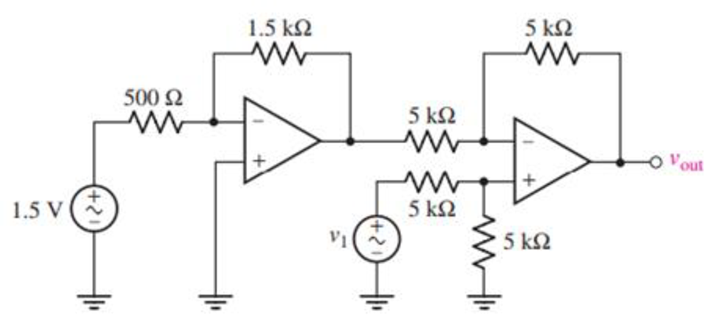
FIGURE 6.50
(a)
Find the output voltage
Answer to Problem 23E
The output voltage
Explanation of Solution
Given data:
The input voltage
Calculation:
The redrawn circuit is shown in Figure 1 as follows.
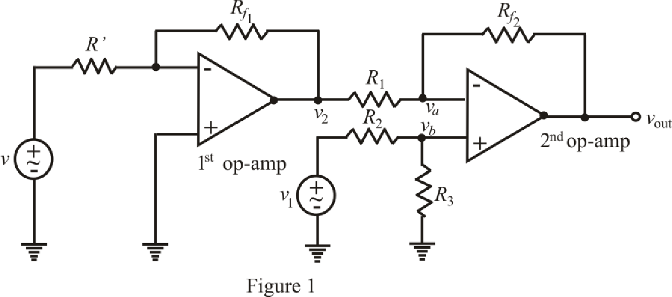
Refer to the Figure 1.
The expression of output voltage for 1st inverting op amp is,
Here,
The expression by the nodal analysis at node
Here,
The expression by the nodal analysis at node
Here,
The expression for the virtual ground concept is as follows,
Refer to the redrawn Figure 1.
Simplify equation (2) as follows.
Rearrange equation (3) for
Substitute
Rearrange for
Substitute for
Substitute
Conclusion:
Thus, the output voltage
(b)
Find the output voltage
Answer to Problem 23E
The output voltage
Explanation of Solution
Given data:
Value of input voltage
Calculation:
Refer to the redrawn Figure 1.
Substitute
Solve for
Conclusion:
Thus, the output voltage
(c)
Find the output voltage
Answer to Problem 23E
The output voltage
Explanation of Solution
Given data:
Value of input voltage
Calculation:
Refer to the redrawn Figure 1.
Substitute
Solve for
Conclusion:
Thus, the output voltage
(d)
Find the output voltage
Answer to Problem 23E
The output voltage
Explanation of Solution
Given data:
Value of input voltage
Calculation:
Refer to the redrawn Figure 1.
Substitute
Solve for
Conclusion:
Thus, the output voltage
Want to see more full solutions like this?
Chapter 6 Solutions
Loose Leaf for Engineering Circuit Analysis Format: Loose-leaf


- 1. Theoretically calculate the voltage across the capacitor in the circuit of Figure 1 when t = 0 s, 5 s, 10 s, 20 s, 30 s, 40 s, and 60 s, assuming that the circuit is under DC conditions when t < 0 s and the switch is opened at t = 0 s. 2. Compare the calculated voltage at t = 20 s with the experimentally measured ∆?.arrow_forwardFind Leq between the terminals a,b for the circuits shown below. Assuming the initial energy stored in the inductors is zero.arrow_forward1. Calculate the capacitance between two parallel plates, each of which is 100 sq. Inches and 2 mm apart in air. 2. A capacitor is charged with 0.23 J of energy at a voltage of 48V. What is its capacitance? 3. A 50-uF capacitor is initially charged. Determine the initial charge of the 50-uF capacitor if the charge transferred to a 100-uF capacitor, when connected in parallel, is 200-uC.arrow_forward
- 6 A capacitor is constructed with parallel metal plates, If the plate separation is 2 mm and the capacitance is given to 1 nano Farads, determine the area of the parallel plates of the device. Select one: a. 0.12 square meters b. 0.23 square meters c. 0.27 square meters d. 0.20 square metersarrow_forwardA 100-pF capacitor is constructed of parallel plates of metal, each having a width W anda length L. The plates are separated by air with a distance d. Assume that L and W are bothmuch larger than d. What is the new capacitance ifa. both L and W are doubled and the other parameters are unchanged?b. the separation d is doubled and the other parameters are unchanged from their initialvalues? c. the air dielectric is replaced with oil having a relative dielectric constant of 25 and theother parameters are unchanged from their initial values ?arrow_forwardA mesh collider a) is as accurate as the triangle count on the mesh b)is the variable optiom for complex meshes such as player characters c)is the only way to get headshots to work d)is faster than a box colliderarrow_forward
- Where do we use SCADA in electrical engineering? Can you please explain the basic principle of it and cite some examples? Please provide answer as long as you want, I'll definitely give a like :)arrow_forwardThe current flowing through a 10-μF capacitor having terminals labeled a and b is i ab =0.3 exp( −2000t ) Afor t≥0 Given that v ab ( 0 )=0, find an expression for v ab (t) for t≥0. Then,find the energy stored in the capacitor for t=∞..arrow_forwardThe following circuit has the following values:R = 40 Ω, L = 2,5 μH and C = 4nF.a)Assuming that the switch has been closed for a long time, determine the capacitor voltage and inductor current values just before opening of the key, that is, at = 0-.b)Calculate the expression for the current i(t), from the moment the switch is opened in t = 0.arrow_forward
- for the circuit represented by the figure, the two resistance values are R=0.752Ω and R2= 1.268 Ω respectively (a) obtain an expression for the energy stored in the capacitor, valid for all t>0; (b) Determine the setting time of the voltage labaled vcarrow_forward4. For the network shown in Fig.4:(a) Determine the mathematical expressions for the variation of the voltage across the capacitor following the closure of the switch at t = 0 on to position 1.(b) When the switch is closed on to position 2 at t = 100 ms, determine the new expression for the capacitor voltage.(c) Plot the voltage waveform for t = 0 to t = 200 ms.arrow_forwardA parallel plate capacitor having area 40 cm2 and plate spacing 1.0 mm is charged to potential difference 600V. Find (a) the capacitance and (b) The energy storedarrow_forward
 Introductory Circuit Analysis (13th Edition)Electrical EngineeringISBN:9780133923605Author:Robert L. BoylestadPublisher:PEARSON
 Delmar's Standard Textbook Of ElectricityElectrical EngineeringISBN:9781337900348Author:Stephen L. HermanPublisher:Cengage Learning
 Programmable Logic ControllersElectrical EngineeringISBN:9780073373843Author:Frank D. PetruzellaPublisher:McGraw-Hill Education
 Fundamentals of Electric CircuitsElectrical EngineeringISBN:9780078028229Author:Charles K Alexander, Matthew SadikuPublisher:McGraw-Hill Education
 Electric Circuits. (11th Edition)Electrical EngineeringISBN:9780134746968Author:James W. Nilsson, Susan RiedelPublisher:PEARSON
 Engineering ElectromagneticsElectrical EngineeringISBN:9780078028151Author:Hayt, William H. (william Hart), Jr, BUCK, John A.Publisher:Mcgraw-hill Education,