
Microelectronics: Circuit Analysis and Design
4th Edition
ISBN: 9780073380643
Author: Donald A. Neamen
Publisher: McGraw-Hill Companies, The
expand_more
expand_more
format_list_bulleted
Videos
Textbook Question
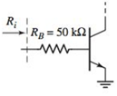
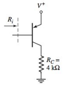
Chapter 6, Problem 6.7P
The parameters of each transistor in the circuits shown in Figure P6.7 are

Expert Solution & Answer
Want to see the full answer?
Check out a sample textbook solution
Students have asked these similar questions
This is a practice question from Electronics Engineering, double sideband supressed carrier problem.
Describe the over-all ac analysis procedure for a common collector.
6)
This MCQ QUESTION FROM ANTENNA ENGINEERING course.
Chapter 6 Solutions
Microelectronics: Circuit Analysis and Design
Ch. 6 - The circuit parameters for the circuit in Figure...Ch. 6 - For the circuit in Figure 6.3, assume transistor...Ch. 6 - For the circuit in Figure 6.14(a), let =90 ,...Ch. 6 - Using the circuit and transistor parameters given...Ch. 6 - Consider the circuit in Figure 6.18. The circuit...Ch. 6 - Repeat Example 6.4 if the quiescent collector...Ch. 6 - For the circuit in Figure 6.31, let RE=0.6k ,...Ch. 6 - Prob. 6.6EPCh. 6 - The parameters of the circuit shown in Figure 6.28...Ch. 6 - For the circuit shown in Figure 6.31, let =100 ,...
Ch. 6 - Design the circuit in Figure 6.35 such that it is...Ch. 6 - For the circuit in Figure 6.28, the smallsignal...Ch. 6 - The circuit in Figure 6.38 has parameters V+=5V ,...Ch. 6 - For the circuit in Figure 6.39, let =125 ,...Ch. 6 - (a) Assume the circuit shown in Figure 6.40(a) is...Ch. 6 - For the circuit in Figure 6.39, let =125 ,...Ch. 6 - Reconsider the circuit in Figure 6.38. Let =120 ,...Ch. 6 - For the circuit shown in Figure 6.48, let =120 ,...Ch. 6 - For the circuit in Figure 6.31, use the parameters...Ch. 6 - Consider the circuit in Figure 6.38. Assume...Ch. 6 - For the circuit shown in Figure 6.49, let VCC=12V...Ch. 6 - Consider the circuit and transistor parameters...Ch. 6 - For the circuit in Figure 6.54, the transistor...Ch. 6 - Assume the circuit in Figure 6.57 uses a 2N2222...Ch. 6 - For the circuit in Figure 6.58, RE=2k , R1=R2=50k...Ch. 6 - Prob. 6.12TYUCh. 6 - For the circuit shown in Figure 6.63, the...Ch. 6 - Prob. 6.14TYUCh. 6 - For the circuit shown in Figure 6.64, let RS=0 ,...Ch. 6 - Consider the circuit in Figure 6.70(a). Let =100 ,...Ch. 6 - In the circuit in Figure 6.74 the transistor...Ch. 6 - Discuss, using the concept of a load line, how a...Ch. 6 - Prob. 2RQCh. 6 - Prob. 3RQCh. 6 - Sketch the hybrid- equivalent circuit of an npn...Ch. 6 - Prob. 5RQCh. 6 - Prob. 6RQCh. 6 - Prob. 7RQCh. 6 - Prob. 8RQCh. 6 - Prob. 9RQCh. 6 - Sketch a simple emitter-follower amplifier circuit...Ch. 6 - Sketch a simple common-base amplifier circuit and...Ch. 6 - Compare the ac circuit characteristics of the...Ch. 6 - Prob. 13RQCh. 6 - Prob. 14RQCh. 6 - (a) Determine the smallsignal parameters gm,r ,...Ch. 6 - (a) The transistor parameters are =125 and VA=200V...Ch. 6 - A transistor has a current gain in the range 90180...Ch. 6 - The transistor in Figure 6.3 has parameters =120...Ch. 6 - Prob. 6.5PCh. 6 - For the circuit in Figure 6.3, =120 , VCC=5V ,...Ch. 6 - The parameters of each transistor in the circuits...Ch. 6 - The parameters of each transistor in the circuits...Ch. 6 - The circuit in Figure 6.3 is biased at VCC=10V and...Ch. 6 - For the circuit in Figure 6.14, =100 , VA= ,...Ch. 6 - Prob. 6.11PCh. 6 - The parameters of the transistor in the circuit in...Ch. 6 - Assume that =100 , VA= , R1=33k , and R2=50k for...Ch. 6 - The transistor parameters for the circuit in...Ch. 6 - For the circuit in Figure P6.15, the transistor...Ch. 6 - Prob. D6.16PCh. 6 - The signal source in Figure P6.18 is s=5sintmV ....Ch. 6 - Consider the circuit shown in Figure P6.19 where...Ch. 6 - Prob. 6.20PCh. 6 - Figure P6.21 The parameters of the transistor in...Ch. 6 - Prob. 6.22PCh. 6 - For the circuit in Figure P6.23, the transistor...Ch. 6 - The transistor in the circuit in Figure P6.24 has...Ch. 6 - For the transistor in the circuit in Figure P6.26,...Ch. 6 - If the collector of a transistor is connected to...Ch. 6 - Consider the circuit shown in Figure P6.13. Assume...Ch. 6 - For the circuit in Figure P6.15, let =100 , VA= ,...Ch. 6 - Consider the circuit in Figure P6.19. The...Ch. 6 - The parameters of the circuit shown in Figure...Ch. 6 - Consider the circuit in Figure P6.26 with...Ch. 6 - For the circuit in Figure P6.20, the transistor...Ch. 6 - In the circuit in Figure P6.22 with transistor...Ch. 6 - For the circuit in Figure P6.24, the transistor...Ch. 6 - Prob. 6.40PCh. 6 - Consider the ac equivalent circuit in Figure...Ch. 6 - For the ac equivalent circuit in Figure P6.42,...Ch. 6 - The circuit and transistor parameters for the ac...Ch. 6 - Consider the circuit in Figure P6.45. The...Ch. 6 - For the transistor in Figure P6.47, =80 and...Ch. 6 - Consider the emitterfollower amplifier shown in...Ch. 6 - The transistor parameters for the circuit in...Ch. 6 - In the circuit shown in Figure P6.51, determine...Ch. 6 - The transistor current gain in the circuit shown...Ch. 6 - Consider the circuit shown in Figure P6.47. The...Ch. 6 - For the circuit in Figure P6.54, the parameters...Ch. 6 - Figure P6.59 is an ac equivalent circuit of a...Ch. 6 - The transistor in the ac equivalent circuit shown...Ch. 6 - Consider the ac equivalent commonbase circuit...Ch. 6 - Prob. 6.62PCh. 6 - The transistor in the circuit shown in Figure...Ch. 6 - Repeat Problem 6.63 with a 100 resistor in series...Ch. 6 - Consider the commonbase circuit in Figure P6.65....Ch. 6 - For the circuit shown in Figure P6.66, the...Ch. 6 - The parameters of the circuit in Figure P6.67 are...Ch. 6 - For the commonbase circuit shown in Figure P6.67,...Ch. 6 - Consider the circuit shown in Figure P6.69. The...Ch. 6 - In the circuit of Figure P6.71, let VEE=VCC=5V ,...Ch. 6 - Consider the ac equivalent circuit in Figure...Ch. 6 - The transistor parameters in the ac equivalent...Ch. 6 - Consider the circuit shown in Figure 6.38. The...Ch. 6 - For the circuit shown in Figure 6.57, the...
Knowledge Booster


Learn more about
Need a deep-dive on the concept behind this application? Look no further. Learn more about this topic, electrical-engineering and related others by exploring similar questions and additional content below.Similar questions
- 6. Through the schematic symbols of MOSFETS, how can you differentiate between a depletion and an enhancement type MOSFET? P-channel or N-channel MOSFET?arrow_forwardDiscuss the similarities and differences between sampling & PAM and show the effects of differences on the spectral characteristics of them?arrow_forwardDraw the transfer curve of logarithmic amplifier.Explain how does a chopper work with basic circuit diagram.arrow_forward
- In a common emitter amplifier. Assume that the coupling capacitor in the collector is shorted. What dc voltage will appear at the collector of the transistor?arrow_forwardDescribe the combined effect of the RC circuits for higher frequency response in a BJT & FETamplifier. the subject : Analogue Electronics IIarrow_forwardWhy do we need to consider small signal analysis while explaining an ACresponse of a transistor?arrow_forward
- What circuit compensates for the greater frequency deviation at the higher modulating signal frequencies?arrow_forwardwhat is the small signal model? Note: the capacitors will be included in the model; ro of the transistors approach infinityarrow_forwardWhat is the function of coupling capacitors? Assuming that they are performing their intended function, how do they appear in the ac equivalent circuit? In general, what effect do coupling capacitors have on the gain of an amplifier as a function of frequency?arrow_forward
- ideally, what should the reactance of a bypass capacitor be in order to eliminate a 10 kHz AC voltage at a given point in an amplifier circuit?arrow_forwardThe parameters for each transistor in the circuit shown in Figure P6.75 areβ = 100 and VA = ∞. (a) Determine the small-signal parameters gm , rπ ,and ro for both transistors. (b) Determine the small-signal voltage gainAv1 = vo1/vs, assuming vo1 is connected to an open circuit, and determinethe gain Av2 = vo/vo1. (c) Determine the overall small-signal voltage gainAv = vo/vs. Compare the overall gain with the product Av1 · Av2, using thevalues calculated in part (b)arrow_forwardSignal designarrow_forward
arrow_back_ios
SEE MORE QUESTIONS
arrow_forward_ios
Recommended textbooks for you
 Introductory Circuit Analysis (13th Edition)Electrical EngineeringISBN:9780133923605Author:Robert L. BoylestadPublisher:PEARSON
 Delmar's Standard Textbook Of ElectricityElectrical EngineeringISBN:9781337900348Author:Stephen L. HermanPublisher:Cengage Learning
 Programmable Logic ControllersElectrical EngineeringISBN:9780073373843Author:Frank D. PetruzellaPublisher:McGraw-Hill Education
 Fundamentals of Electric CircuitsElectrical EngineeringISBN:9780078028229Author:Charles K Alexander, Matthew SadikuPublisher:McGraw-Hill Education
 Electric Circuits. (11th Edition)Electrical EngineeringISBN:9780134746968Author:James W. Nilsson, Susan RiedelPublisher:PEARSON
 Engineering ElectromagneticsElectrical EngineeringISBN:9780078028151Author:Hayt, William H. (william Hart), Jr, BUCK, John A.Publisher:Mcgraw-hill Education,
Introductory Circuit Analysis (13th Edition)
Electrical Engineering
ISBN:9780133923605
Author:Robert L. Boylestad
Publisher:PEARSON
Delmar's Standard Textbook Of Electricity
Electrical Engineering
ISBN:9781337900348
Author:Stephen L. Herman
Publisher:Cengage Learning
Programmable Logic Controllers
Electrical Engineering
ISBN:9780073373843
Author:Frank D. Petruzella
Publisher:McGraw-Hill Education
Fundamentals of Electric Circuits
Electrical Engineering
ISBN:9780078028229
Author:Charles K Alexander, Matthew Sadiku
Publisher:McGraw-Hill Education
Electric Circuits. (11th Edition)
Electrical Engineering
ISBN:9780134746968
Author:James W. Nilsson, Susan Riedel
Publisher:PEARSON
Engineering Electromagnetics
Electrical Engineering
ISBN:9780078028151
Author:Hayt, William H. (william Hart), Jr, BUCK, John A.
Publisher:Mcgraw-hill Education,
02 - Sinusoidal AC Voltage Sources in Circuits, Part 1; Author: Math and Science;https://www.youtube.com/watch?v=8zMiIHVMfaw;License: Standard Youtube License