
CONTROL SYSTEMS ENGINEERING
7th Edition
ISBN: 9781119185666
Author: NISE
Publisher: WILEY
expand_more
expand_more
format_list_bulleted
Concept explainers
Videos
Textbook Question
Chapter 6, Problem 69P
Hybrid vehicle. Figure P6.l8 shows the HEV system presented in Chapter 5, where parameter values have
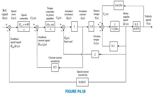
been substituted. It is assumed here that the speed controller has a proportional gain, Kp, to be adjusted. Use the Routh-Hurwitz stability method to find the range of positive Kp, for which the system is closed-loop stable (Graebe, I995).
Expert Solution & Answer
Want to see the full answer?
Check out a sample textbook solution
Students have asked these similar questions
A system has the following characteristic equation: s+ s+ 3s+ 2s + 2 = 0
Using the Routh-Hurwitz method, checka. How many roots are to the right of the imaginary axis?b. Is the system stable?.
Q(s) = S5 + 2S4 + 2S3 + 4S2 + 11S + 10 = 0
i). Identify the stability of the system using Routh Hurwitz Algorithm.
(ii). Comment about the Roots location.
b. Use Routh - Hurwitz stability criterion to determine the system having the following
function is stable.
s 3+ 3s?+ 7s +k = 0
Chapter 6 Solutions
CONTROL SYSTEMS ENGINEERING
Ch. 6 - Prob. 1RQCh. 6 - Prob. 2RQCh. 6 - What would happen to a physical system chat...Ch. 6 - Why are marginally stable systems considered...Ch. 6 - Prob. 5RQCh. 6 - Prob. 6RQCh. 6 - Prob. 7RQCh. 6 - Prob. 8RQCh. 6 - Prob. 9RQCh. 6 - Why do we sometimes multiply a row of a Routh...
Ch. 6 - Prob. 11RQCh. 6 - Prob. 12RQCh. 6 - 13. Does the presence of an entire row of zeros...Ch. 6 - Prob. 14RQCh. 6 - Prob. 15RQCh. 6 - Prob. 16RQCh. 6 - Tell how many roots of the following polynomial...Ch. 6 - Tell how many roots of the following polynomial...Ch. 6 - Using the Routh table, tell how many poles of the...Ch. 6 - Prob. 4PCh. 6 - Determine how many closed-loop poles lie in the...Ch. 6 - Determine how many closed-loop poles lie in the...Ch. 6 - MATLAB ML 7. Use MATLAB to find the pole location...Ch. 6 - Symbolic Math SM 8. Use MATLAB and the Symbolic...Ch. 6 - Determine whether the unity feedback system of...Ch. 6 - Use MATLAB to find the pole locations for the...Ch. 6 - Consider the unity feedback system of Figure P6.3...Ch. 6 - In the system of Figure P6.3, let Gs=Ks+1ss2s+3...Ch. 6 - Given the unity feedback system of Figure P6.3...Ch. 6 - Using the Routh-Hurwitz criterion and the unity...Ch. 6 - Given the unity feedback system of Figure P6.3...Ch. 6 - Repeat Problem 15 using MATLAB.Ch. 6 - Prob. 17PCh. 6 - For the system of Figure P6.4, tell how many...Ch. 6 - Using the Routh-Hurwitz criterion, tell how many...Ch. 6 - Determine if the unity feedback system of Figure...Ch. 6 - For the unity feedback system of Figure P6.3 with...Ch. 6 - In the system of Figure P6.3, let Gs=Ksassb Find...Ch. 6 - For the unity feedback system of Figure P63 with...Ch. 6 - Find the range of K for stability for the unity...Ch. 6 - For the unity feedback system of Figure P6.3 with...Ch. 6 - find the range of K for stability. [Section: 6.41]...Ch. 6 - Find the range of gain, K, to ensure stability in...Ch. 6 - Using the Routh-Hurwitz criterion, find the value...Ch. 6 - Use the Routh-Hurwitz criterion to find the range...Ch. 6 - Prob. 32PCh. 6 - Given the unity feedback system of Figure P63 with...Ch. 6 - Repeat Problem 33 for [Section: 6.4]...Ch. 6 - For the system shown in Figure P6.8, find the...Ch. 6 - Given the unity feedback system of Figure P6.3...Ch. 6 - For the unity feedback system of Figure P6.3 with...Ch. 6 - For the unity feedback system of Figure P6.3 with...Ch. 6 - Given the unity feedback system of Figure P6.3...Ch. 6 - Using the Routh-Hurwitz criterion and the unity...Ch. 6 - Find the range of K to keep the system shown in...Ch. 6 - Prob. 43PCh. 6 - The closed-loop transfer function of a system is...Ch. 6 - Prob. 45PCh. 6 - Prob. 46PCh. 6 - An interval polynomial is of the form...Ch. 6 - A linearized model of a torque-controlled crane...Ch. 6 - The read/write head assembly arm of a computer...Ch. 6 - A system is represented in state space as...Ch. 6 - State Space SS 52. The following system in state...Ch. 6 - Prob. 54PCh. 6 - A model for an airplane’s pitch loop is shown in...Ch. 6 - Prob. 57PCh. 6 - Prob. 58PCh. 6 - Prob. 59PCh. 6 - Prob. 60PCh. 6 - Prob. 61PCh. 6 - Look-ahead information can be used to...Ch. 6 - Prob. 63PCh. 6 - It has been shown (Pounds, 2011) that an unloaded...Ch. 6 - Prob. 65PCh. 6 - The system shown in Figure P6.16 has G1s=1/ss+2s+4...Ch. 6 - Prob. 67PCh. 6 - Prob. 68PCh. 6 - Hybrid vehicle. Figure P6.l8 shows the HEV system...Ch. 6 - Prob. 70P
Knowledge Booster


Learn more about
Need a deep-dive on the concept behind this application? Look no further. Learn more about this topic, mechanical-engineering and related others by exploring similar questions and additional content below.Similar questions
- P6. The open loop transfer function of a unity feedback system is K(s+2) G (s) = s(s+3)(s²+2s+10) 1- Find the value of K so that the error steady state for the unit ramp input r(t)=t is less than or equal to 0.01. 2-For the value of K found in part (1), use the Routh method to verify whether the closed loop system is stable.arrow_forward2- Using Matlab, what are the step response curves of the closed-loop system, as shown in fig.1. the feedback represents the second-order dynamic system. (fill in the following table) For=0.4 Wn 1 3 6 9 10 R(S) 0.1 0.3 0.6 0.9 1 For w 5 rad/sec 3 Settling time Peak response 2 Wn s(s+23wn) Settling time Peak response C(s) Discuss the follow Which parameters or w occur on the rise time of the response? Which parameter increases the speed of response? Which parameters can be decreases the response amplitude? Which parameter decreases the steady error state? fig.2arrow_forwardQ5) For unity feedback control system with forward transfer function (G(s) ): G(s) = ; By using root locus graph calculate the value K(s+5) (s+2)(s²+12s+50) of gain (K) which must be added to get the dominant root at damping ratio (-0.886) and natural frequency (w = 8 rad/sec )? www CTRICAL ENGINarrow_forward
- For the given close-loop system transfer function, determine its stability using Routh-Hurwitz Test for Stability.1. What is the stability of the system? (Stable, Unstable, Marginally Stable)arrow_forwardxa 0- 1 point) Which of the systems presented on Fig. 2 is stable and which unstable? (a) t Fig. 2. System response (b) Aarrow_forwardb. Using Simulink, simulate the transfer function airflow response, Q(t) (air entering respiratory system) for a sine wave input pressure Pao(t)= 2.5 cm·H2O (i.e. 5 cm·H2O peak-to-peak) at 15 breaths min' (or 0.25 Hz) for each lung model. Use the following parameters: -1 i. RC model: R= 1cm·H2O's L' and C=0.2 L·cm·H2O¯ RIC model: R= 1cm·H2O's·L', C= 0.2 L·cm·H2O¯ , and I= 0.01 cm·H2O L-s² Two-compartment model: R. = lcm H2O's L', Rp1,2 = 0.5 cm·H2O•s·L', Cp1,2=0.2 L·cm·H2O', and I= 0.01 cm H2O·L-•s² Mead model: R. = 1cm·H2O•s L', Rp = 0.5 cm:H2O•s·L', C1 =0.2 L·cm·H2O', Cw=0.2 L·cm·H2O-', C, =0.005 L·cm·H2O', and I= 0.01 cm H2O·L-1·s² ii. iii. iv.arrow_forward
- P6. The open loop transfer function of a unity feedback system is K(s+2) G(s) = s(s+3) (s²+2s+10) 1- Find the value of K so that the error steady state for the unit ramp input r(t)=t is less than or equal to 0.01.arrow_forward4G I. 3:22 A moodle1.du.edu.om Consider the 3 degree of freedom robot manipulator as shown in the figure Link 3 Länk 2 Trint 1 The objective is to find the kinematics inverse of the robot Px=0.9 m, Py=0.6, L1=1.5m, L2=1.5m and qz= 2 rad The value of cos(q2) is equal to Choose... + The positive value of sin(q2) is equal to Choose... + The value of q2 in rad is Choose... + The value of qı in rad is Choose... + The value of q3 in rad is Choose... +arrow_forwardA position system is modeled by an ODE: d²x(t) dt? dx(t) +4 dt + 13x(t) = u(t) Compute the Laplace Transform of the system and its transfer function G(s) = X) u(s) where x(t) is the output and u(t) is the input. Assume the initial conditions are zeroes.arrow_forward
- For the system with open loop transfer function given by R(s) K s(s + 1) (s² + 4s +13) where K is the feedback gain. Sketch the root locus a) How many asymptotes are there for this system's root locus? what are asymptote angles? What is the center of asymptotes? C(s) b) Does the root locus cross the imaginary axis? where and what is the value of K at that point? c) Is there any break away, break in points? What is the approximate values of these points?arrow_forwardWhat is the step response of the dynamic system pictured below?arrow_forwardGiven the vibrating system below: K4 Y(t) =Ysin30t where for = 30 and Y=20mm Find the following K1 K2 m C3 H C2 C1 C5 C4 1. Frequency Ratio 2. Displacement Transmissibility Ratio 3. Absolute displacement of the mass 4. Type of Damping 5. Equation of motion x(t). Assume Initial conditions for displacement and velocity 6. Graph 2 cycles of the vibrating system. You can use third party app for this. M = 10 kg K1=100 N/m K2= 80 N/m K3=75 N/m K4= 120 N/m C1 = 20Ns/m C2=40 Ns/m C3= 35Ns/m C4= 15 Ns/m C5= 10 Ns/marrow_forward
arrow_back_ios
SEE MORE QUESTIONS
arrow_forward_ios
Recommended textbooks for you
 Principles of Heat Transfer (Activate Learning wi...Mechanical EngineeringISBN:9781305387102Author:Kreith, Frank; Manglik, Raj M.Publisher:Cengage Learning
Principles of Heat Transfer (Activate Learning wi...
Mechanical Engineering
ISBN:9781305387102
Author:Kreith, Frank; Manglik, Raj M.
Publisher:Cengage Learning
Introduction to Undamped Free Vibration of SDOF (1/2) - Structural Dynamics; Author: structurefree;https://www.youtube.com/watch?v=BkgzEdDlU78;License: Standard Youtube License