
Videos
Predict the relative brightness of bulbs
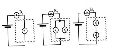
What does your prediction imply about the relative currents through the batteries? Explain.
Have a tutorial instructor show you these circuits so that you can check your answers.
Resolve any conflicts between your answers and your observations.

Learn your wayIncludes step-by-step video

Chapter 6 Solutions
Tutorials in Introductory Physics
Additional Science Textbook Solutions
Conceptual Physics (12th Edition)
Applied Physics (11th Edition)
Essential University Physics: Volume 1 (3rd Edition)
Lecture- Tutorials for Introductory Astronomy
Physics: Principles with Applications
Essential University Physics: Volume 2 (3rd Edition)


- Consider the circuit below (picture attached) How would you add a resistor with a resistance of 7.00 Ω to the circuit so that the current through the 3.0 Ω resistor is maximized? (This is already answered but I believe this correlates with part b. For this part the new resistor must be in parallel with the 4 ohm resistor) By how much does the current through 3.0 Ω resistor increase when you do what was descibed above? (Must be in units of ampheres please.)arrow_forwardConsider the circuit configurations below, where two lightbulbs are connected to a single battery in different ways. Based on what you learned about parallel and series connections in lab, which of these two configurations would result in the light bulbs being the brightest? Fully explain your reasoning. Imagine that you are given four 100Ω resistors to build a circuit. Your challenge is to use all four of the resistors in the circuit, but the circuit must have an overall equivalent resistance of 100Ω. Is this possible? If so, draw a diagram of the circuit and explain how the connections result in a 100Ω equivalent resistance. If this is not possible, draw a diagram of a circuit involving all four resistors that has an equivalent resistance as close to 100Ω as is possible.arrow_forwardThe diagram at the right shows two identical resistors - R1 and R2 - placed in a circuit with a 12-Volt battery. Use this diagram to answer the question. These two resistors are connected in ____. a. series b. parallel c. neitherarrow_forward
- Consider the diagram at the right of a parallel circuit. Each light bulb has an identical resistance of R and the battery voltage is V. Use the labeled points on the diagram to answer the following questions. a. If the current at location A is I amperes, then the current at location B is ____ amperes. (Answer in terms of I.) b. If the current at location A is I amperes, then the current at location D is ____ amperes. (Answer in terms of I.) c. If the current at location A is I amperes, then the current at location L is ____ amperes. (Answer in terms of I.) d. If the voltage of the battery is doubled, then the current at location A would be ____ (two times, four times, one-half, one-fourth, etc.) the original value. e. If the voltage of the battery is doubled, then the current at location B would be ____ (two times, four times, one-half, one-fourth, etc.) the original value. f. If the voltage of the battery is doubled, then the current at location D would be ____ (two times, four times,…arrow_forwardSolve the unknown quantities I1, I2 and I3 from the circuit in the picture. b) What is the voltage between points A and B?arrow_forwardThree resistors having resistances of 4.0 Ω, 6.0 Ω, and 10.0 Ω are now connected in series. If the combination is connected to an ideal 12-V. What is the total resistance of the circuit? What is the current through each resistor? What is the voltage drop across each resistor? What is the power dissipated by the 6.0 Ω resistor? Clearly state the formulae you’re using and what your letters/symbols mean.arrow_forward
- Refer to the circuit on the side. (a) Find the total resistance of the external circuit RT, considering an ohmmeter is connected at terminals 1 and 2. Refer to the figure on the side. (b) When an ideal battery of 10v is connected to terminals 1 and 2, what is the current passing through the 5 Ω resistor?arrow_forwardPart a and b, please. For the circuit shown in the figure (Figure 1) both meters are idealized, the battery has no appreciable internal resistance, and the ammeter reads 1.60 A Part a What does the voltmeter read? Part b What is the emf E of the battery?arrow_forwardWhat will happen to the brightness of bulb A if the circuit will be added a bulb B with the same value of A in parallel connection? Why? If the five cells of question 1 are connected in parallel the resulting battery will have:arrow_forward
- 2. What are the resistances R and the emf of the battery in the circuit below? 3. Find I1, I2 and the emf in the battery on the right in the circuit below. Please show all stepsarrow_forwardConsider the circuit below (Figure B) Find current I3 at the node shown below. Show your ENCODED solution. Currents I1 and I2 are flowing into the node and currents I3 and I4 are flowing out of the node. Apply Kirchhoff's law of current at the given node. ∑ ?? = ∑ ???arrow_forward
 Glencoe Physics: Principles and Problems, Student...PhysicsISBN:9780078807213Author:Paul W. ZitzewitzPublisher:Glencoe/McGraw-Hill