
Tutorials in Introductory Physics
1st Edition
ISBN: 9780130970695
Author: Peter S. Shaffer, Lillian C. McDermott
Publisher: Addison Wesley
expand_more
expand_more
format_list_bulleted
Videos
Textbook Question
Chapter 6.1, Problem 4aT
The circuit at tight contains three identical bulbs and an ideal battery. Assume that the resistance of the switch, when closed, is negligible. Use the model we have developed to:
• predict the relative brightness of the bulbs in the circuit with the switch closed. Explain.
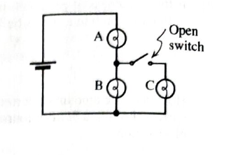
• predict how the brightness of bulb A changes when the switch is opened. Explain.
Expert Solution & Answer

Learn your wayIncludes step-by-step video

schedule03:10
Students have asked these similar questions
Consider the circuit configurations below, where two lightbulbs are connected to a single battery in different ways. Based on what you learned about parallel and series connections in lab, which of these two configurations would result in the light bulbs being the brightest? Fully explain your reasoning.
Imagine that you are given four 100Ω resistors to build a circuit. Your challenge is to use all four of the resistors in the circuit, but the circuit must have an overall equivalent resistance of 100Ω. Is this possible?
If so, draw a diagram of the circuit and explain how the connections result in a 100Ω equivalent resistance. If this is not possible, draw a diagram of a circuit involving all four resistors that has an equivalent resistance as close to 100Ω as is possible.
Consider the circuit below (picture attached)
How would you add a resistor with a resistance of 7.00 Ω to the circuit so that the current through the 3.0 Ω resistor is maximized? (This is already answered but I believe this correlates with part b. For this part the new resistor must be in parallel with the 4 ohm resistor)
By how much does the current through 3.0 Ω resistor increase when you do what was descibed above? (Must be in units of ampheres please.)
Part A5
Show all work picture attatched
Given the following electric circuit
It is known that the voltage measured by the voltmeter is 5 Volt
Calculate the value of the current Ibat through the battery BAT1 (It is the current that the amperemeter shows)
Calculate the value of the Resistance R1
Calculate the Power provided por the battery to the system
Calculate the Power released by each one of the Resistances R1, R2, and R3
Explain if there is a relation between the Power provided por the battery Pbat and the Power released by the Resistances R1, R2, and R3. Justify your answer with your calculations
Type your solution of questions 1) to 5) in RED or PASTE the image of your handwriting solution HERE
Chapter 6 Solutions
Tutorials in Introductory Physics
Ch. 6.1 - Obtain a battery, a light bulb, and a single piece...Ch. 6.1 - A student has briefly connected a wire across the...Ch. 6.1 - Light a bulb using a battery and a single wire....Ch. 6.1 - Carefully examine a bulb. Two wires extend from...Ch. 6.1 - Compare the brightness of the two bulb with each...Ch. 6.1 - Compare the brightness of each of the bulbs in the...Ch. 6.1 - We may think of a bulb as percentage an obstacle,...Ch. 6.1 - Compare the brightness of the bulbs in this...Ch. 6.1 - Is the brightness of each bulb in the two-bulb...Ch. 6.1 - Formulate a rule for predicting how the current...
Ch. 6.1 - Does the amount of current through a battery seem...Ch. 6.1 - Unscrew one of the bulbs in the two-bulb parallel...Ch. 6.1 - The circuit at tight contains three identical...Ch. 6.1 - Show that a simple application of the model for...Ch. 6.2 - The circuits at right contain identical batteries,...Ch. 6.2 - The circuits at right contain identical batteries...Ch. 6.2 - Predict the relative brightness of bulbs...Ch. 6.2 - Set up the circuit with a single bulb and the...Ch. 6.2 - Set up the circuit containing two bulbs in series...Ch. 6.2 - Predict what the voltmeter would read if it were...Ch. 6.2 - Set up the circuit with two bulbs in parallel as...Ch. 6.2 - Answer the following questions based on the...Ch. 6.2 - Set up the circuit with three bulbs as shown and...Ch. 6.2 - Before setting up the circuit shown at right:...Ch. 6.2 - Both circuits al right have more than one path for...Ch. 6.3 - A capacitor is connected to a battery, bulb, and...Ch. 6.3 - Remove the capacitor and the bulb from the...Ch. 6.3 - Suppose an uncharged capacitor is connected in...Ch. 6.3 - Suppose that instead of connecting the uncharged...Ch. 6.3 - Suppose that the bulbs were connected in parallel...Ch. 6.3 - After completing the experiments above, two...Ch. 6.3 - Suppose that a different capacitor of smaller...Ch. 6.3 - Before connecting the circuit a student makes the...Ch. 6.3 - Make the following prediction on the basis of your...
Additional Science Textbook Solutions
Find more solutions based on key concepts
17. 350 cm2 = _______m2
Applied Physics (11th Edition)
Professional Application Football coaches advise players to block, hit, and tackle with their feet on the groun...
College Physics
The dielectric constant of the material between the plates.
Physics (5th Edition)
1. When is energy most evident?
Conceptual Physics (12th Edition)
3. What is free-fall, and why does it make you weightless? Briefly describe why astronauts are weightless in th...
The Cosmic Perspective (8th Edition)
The pV-diagram of the Carnot cycle.
Sears And Zemansky's University Physics With Modern Physics
Knowledge Booster


Learn more about
Need a deep-dive on the concept behind this application? Look no further. Learn more about this topic, physics and related others by exploring similar questions and additional content below.Similar questions
- Identical bulbs are shown in the circuit. 1) Is bulb A brighter, dimmer, or the same brightness as bulb B? Explain 2) Is the current through bulb D greater that or less that, or equal to the current through bulb F. Explain. 3) If bulb F is unscrewed from its socket, does bulb B become brighter, dimmer, or stay the same. Explain.arrow_forwardGiving the circuit presented below calculate: 3) Determine which ONE switch, between SW1, SW2, and SW3, YOU need to close to cause the current of the battery to increases the most. What is the values of this current? 4) Calculate the value of the current through the battery and the Voltage across all the resistors VR1, VR2 and VR3 when the switches SW1 and SW3 are closed, and the switch SW2 is openarrow_forwardIn a parallel circuit, is the current different for each resistor? Explain. In a parallel circuit, is the voltage different at each resistor? Explain. In a parallel circuit, does the current increase if the resistance increases? Explain. Can the electric circuit in your house be considered a parallel circuit? Explain.arrow_forward
- 3. What is the potential difference across the 6.0 Ω resistor in the circuit shown? please hand write it or make it very clear to understand.arrow_forwardPart D) Now apply the loop rule to loop 1 (the larger loop spanning the entire circuit). Sum the voltage changes across each circuit element around this loop going in the direction of the arrow. Express the voltage drops in terms of Vb, I1, I3, the given resistances, and any other given quantities. Answer=Σ(ΔV)=0= It is still saying incorrect because the correct answer does not depend on: I2, R2. Can you explain why that is and what the correct equation would be?arrow_forward1) What are the units of the slope of the line? 2) How would you use the slope to calculate the resistance of each resistor? Hint: use the units to guide your thinking here. 3) Please use your graphs to calculate the resistance of each resistor. Then, please find the percent error between your calculated values and the measured value (9.7 ㏀) of each resistor.arrow_forward
- Describe how the current flowing through the resistor varied as the voltage was increased? Based on the graph, What do the slopes of the best fit lines represent? Explain Do you consider the resistor as ohmic? Why or why not?arrow_forwardPhysics R1.) What is the importance of drawing the schematic diagram of electric circuits in house planning? Why?arrow_forwardIn your estimation would VT =IR1 + IR2 +IR3 +….. be true for all series resistive strings? Explain. Do you believe that the measured current is the same at all points of a series resistive string when a potential difference is present acrossthe circuit? Explain. Could you always expect that RT = R1 + R2 + R3 +…… in a series resistive circuit? Explain.arrow_forward
- The rectangular block below has front-face dimensions of 10 cm by 4 cm, with a depth of 3 cm.(Figure 1) You will be asked to treat this object as an electrical resistor. Rank the block based on its electrical resistance along the three illustrated coordinate directions (x, y, and z). If all of the dimensions of the block double (to become 20 cm wide, 8 cm tall, and 6 cm deep), what happens to the resistance along each axis? The resistance quadruples. The resistance doubles. The resistance stays the same. The resistance is halved. The resistance is quartered.arrow_forwardA circuit contains three identical bulbs lit by connection to a single battery. When a wire is connected across the terminals of one of the bulbs, it goes out and so does another one of the bulbs. The remaining bulb becomes brighter. a.) Sketch the circuit in which the two bulbs must have been arranged. Explain reasoning b.) What would happen to the brightness of the other two bulbs if the wire were connected across the terminals of the bulb that does not go out in part (a)?arrow_forwardHelp please, Show your complete (step-by-step) analysis and solution, with the appropriate equations and/or diagrams. Thank youu! 1. Originally, a circuit contains four (4) identical resistors in parallel across a battery. If one resistor is removed, what happens to the value of total current, total resistance and total voltage? Express the new quantities in terms of the original quantities.arrow_forward
arrow_back_ios
SEE MORE QUESTIONS
arrow_forward_ios
Recommended textbooks for you
 Glencoe Physics: Principles and Problems, Student...PhysicsISBN:9780078807213Author:Paul W. ZitzewitzPublisher:Glencoe/McGraw-Hill
Glencoe Physics: Principles and Problems, Student...
Physics
ISBN:9780078807213
Author:Paul W. Zitzewitz
Publisher:Glencoe/McGraw-Hill
Series & Parallel - Potential Divider Circuits - GCSE & A-level Physics; Author: Science Shorts;https://www.youtube.com/watch?v=vf8HVTVvsdw;License: Standard YouTube License, CC-BY