
Videos
Set up the circuit with three bulbs as shown and observe their brightness.
Before making the voltmeter measurements, predict the ranking of the potential difference across the battery and each bulb
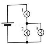
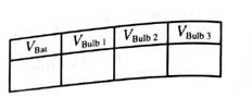
Measure the potential difference across each element in the circuit. If your measurement are not consistent with your ranking above, resolve the inconsistencies.

Learn your wayIncludes step-by-step video

Chapter 6 Solutions
Tutorials in Introductory Physics
Additional Science Textbook Solutions
University Physics with Modern Physics (14th Edition)
University Physics (14th Edition)
University Physics Volume 2
Physics: Principles with Applications
College Physics
College Physics: A Strategic Approach (4th Edition)


- What will happen to the brightness of bulb A if the circuit will be added a bulb B with the same value of A in parallel connection? Why? If the five cells of question 1 are connected in parallel the resulting battery will have:arrow_forwardRefer to the circuit on the side. (a) Find the total resistance of the external circuit RT, considering an ohmmeter is connected at terminals 1 and 2. Refer to the figure on the side. (b) When an ideal battery of 10v is connected to terminals 1 and 2, what is the current passing through the 5 Ω resistor?arrow_forwardConsider the circuit shown in (Figure 1). Assume E = 12 V. What is the equivalent capacitance? What is the charge on 3.0 μF capacitor? What is the charge on 4.0 μF capacitor? What is the charge on 6.0 μF capacitor?arrow_forward
- Can the circuit be reduced to the equivalent of 1? What would that look like? If the two batteries could be be replaced by only one what is its equivalent value? Write the conservation of current on the nodes of the original circuit using A1, B2,etc. Indicate election of notation on the circuit What is the conservation of difference of potential on the original circuit using the notation ∆?, ∆?1, ∆?2 Indicate the election of the notation on the circuit. Find the value of each difference of potential in V Find the value of each current in Amperesarrow_forwardGiven a 10 uF capacitor and a 14 uF capacitor, what are all of the equivalentcapacitances that you can create by connecting them together?Now for each configuration that you have above, imagine that you connect 12V across the full circuit. What is the energy for the 10 uF and 14 uF capacitor in each configuration that you determined above?arrow_forwardFor the circuit shown:1. Calculate the values of ammeters and voltmeters?2. Which one of the following is true?A) IT = I1 =I2 = I3 B) IITT = VV1RR1+ VV2RR2+ VV3RR3 C) VVTT = VV1 + VV2 + VV3 D) IITT = VVRR1= VVRR2= VVRR3 3. What is the object of this experiment?arrow_forward
- Consider the circuit below. Using Kirchhoff rules, determine the current through the resistor R2?arrow_forwardWhat happens to bulbs B and C if there is a short placed across bulb Aas shown below? Explain your reasoning.arrow_forwardPart a and b, please. For the circuit shown in the figure (Figure 1) both meters are idealized, the battery has no appreciable internal resistance, and the ammeter reads 1.60 A Part a What does the voltmeter read? Part b What is the emf E of the battery?arrow_forward
- Three resistors R1 = 10 Ω, R2 = 20 Ω, and R3 = 30 Ω are in series and are connected to a voltage supply that provides 15.3 V of voltage as shown in the circuit diagram below. Answer the following questions a) What is the total resistance of the three resistors? (b) What is the electric current at point A, B, C, and D? (c) What is the electrical potential difference between point B and point C in the circuit? (d) What is the electrical potential difference between point B and point D in the circuit? (e) Find the power dissipation in the resistor R1 when the voltage at the voltage supply is increased to 21 V.arrow_forwardHelp please, Show your complete (step-by-step) analysis and solution, with the appropriate equations and/or diagrams. Thank youu! 1. Originally, a circuit contains four (4) identical resistors in parallel across a battery. If one resistor is removed, what happens to the value of total current, total resistance and total voltage? Express the new quantities in terms of the original quantities.arrow_forwardTake three resistors.R1=25 ohms, R2=17 ohms and R3 = 3 ohms. Let V0 = 30 V. Now, connect the resistors as shown in the figure, and connect them to the power supply. Record the voltage across each resistor, using the voltmeter. a. Are the voltages V1, V2 and V3 equal to each other? Why or why not? b. Calculate the total voltage V = V1 + V2 + V3. Explain why it has the value it does. c. Use Ohm’s law to calculate the current through each resistor. d. Calculate the effective resistance of the circuit. e. Construct another circuit by replacing the 3 resistors with the single effective resistance. please solve all points..arrow_forward
 College PhysicsPhysicsISBN:9781305952300Author:Raymond A. Serway, Chris VuillePublisher:Cengage Learning
 University Physics (14th Edition)PhysicsISBN:9780133969290Author:Hugh D. Young, Roger A. FreedmanPublisher:PEARSON
 Introduction To Quantum MechanicsPhysicsISBN:9781107189638Author:Griffiths, David J., Schroeter, Darrell F.Publisher:Cambridge University Press
 Physics for Scientists and EngineersPhysicsISBN:9781337553278Author:Raymond A. Serway, John W. JewettPublisher:Cengage Learning
 Lecture- Tutorials for Introductory AstronomyPhysicsISBN:9780321820464Author:Edward E. Prather, Tim P. Slater, Jeff P. Adams, Gina BrissendenPublisher:Addison-Wesley
 College Physics: A Strategic Approach (4th Editio...PhysicsISBN:9780134609034Author:Randall D. Knight (Professor Emeritus), Brian Jones, Stuart FieldPublisher:PEARSON