EP ENGR.MECH.-MOD.MASTERING ACCESS
15th Edition
ISBN: 9780134867267
Author: HIBBELER
Publisher: PEARSON CO
expand_more
expand_more
format_list_bulleted
Concept explainers
Videos
Textbook Question
Chapter 7, Problem 105P
If x = 2 ft and the crate weighs 300 lb, which cable segment AB, BC, or CD has the greatest tension? What is this force and what is the sag yB?
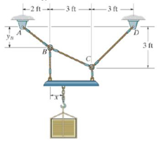
Probs. 7–105/106
Expert Solution & Answer
Want to see the full answer?
Check out a sample textbook solution
Students have asked these similar questions
The cable supports a girder which weighs 850 lb/ft.
Determine the tension in the cable at points A, B, and C.
-100 ft-
40 ft
20 ft
At point B, take x=0 and y=0 (origin point). So, Which following one is TRUE?
4/7 Determine the force in each member of the loaded
truss. Make use of the symmetry of the truss and of
the loading.
В
D
4 m
E
5 m
5 m
5 m
5 m
A
H
G
F
30 kN
60 kN
30 kN
-4 ft-
5 ft
R
4 ft
A
B
(6,0,4) ft
Given that the force in cable AB has a magnitude of TAB = 8 lbs and the unit vector
in the direction of TAB is UAB=0.4361 -0.873j -0.218k. What is the moment reaction
at the fixed support C? C and A have the same y-component.
-65.5i -45.8j +52.4k ft-lb
-52.41 -36.6j +41.9k ft-lb
+52.4i +36.6j -41.9k ft-lb
+65.5i +45.8j-52.4k ft-lb
+34.91 +24.4j -27.9k ft-lb
-34.91 -24.4j +27.9k ft-lb
Chapter 7 Solutions
EP ENGR.MECH.-MOD.MASTERING ACCESS
Ch. 7 - Determine the normal force, shear force, and...Ch. 7 - Determine the normal force, shear force, and...Ch. 7 - Determine the normal force, shear force, and...Ch. 7 - Determine the normal force, shear force, and...Ch. 7 - Determine the normal force, shear force, and...Ch. 7 - Determine the normal force, shear force, and...Ch. 7 - Determine the shear force and moment at points C...Ch. 7 - The pliers are used to grip the tube at B. If a...Ch. 7 - Determine the distance a as a fraction of the...Ch. 7 - The cable will fail when subjected to a tension of...
Ch. 7 - Determine the distance a between the bearings in...Ch. 7 - The cantilevered rack is used to support each end...Ch. 7 - Rod AB is fixed to a smooth collar D, which slides...Ch. 7 - Prob. 22PCh. 7 - Determine the normal force, shear force, and...Ch. 7 - The distributed loading W = W0 sin , measured per...Ch. 7 - Solve Prob. 7-39 for = 120. Probs. 739/40Ch. 7 - Determine the x, y, z components of force and...Ch. 7 - Determine the x, y, z components of internal...Ch. 7 - Determine the shear and moment as a function of x,...Ch. 7 - Determine the shear and moment as a function of x,...Ch. 7 - Determine the shear and moment as a function of x,...Ch. 7 - Determine the shear and moment as a function of x,...Ch. 7 - Determine the shear and moment as a function of x,...Ch. 7 - Determine the shear and moment as a function of x,...Ch. 7 - Draw the shear and moment diagrams for the shaft...Ch. 7 - Draw the shear and moment diagrams for the beam...Ch. 7 - Draw the shear and moment diagrams for the beam...Ch. 7 - Draw the shear and moment diagrams for the...Ch. 7 - Draw the shear and moment diagrams of the beam (a)...Ch. 7 - If L = 9 m, the beam will fail when the maximum...Ch. 7 - Draw the shear and moment diagrams for the beam....Ch. 7 - Draw the shear and moment diagrams for the beam....Ch. 7 - The shaft is supported by a smooth thrust bearing...Ch. 7 - Draw the shear and moment diagrams for the beam....Ch. 7 - Prob. 58PCh. 7 - Prob. 59PCh. 7 - The shaft is supported by a smooth thrust bearing...Ch. 7 - Draw the shear and moment diagrams for the beam....Ch. 7 - Prob. 65PCh. 7 - Draw the shear and moment diagrams for the beam....Ch. 7 - Draw the shear and moment diagrams for the beam....Ch. 7 - Draw the shear and moment diagrams for the beam....Ch. 7 - Draw the shear and moment diagrams for the beam....Ch. 7 - Draw the shear and moment diagrams for the beam....Ch. 7 - Draw the shear and moment diagrams for the beam....Ch. 7 - Draw the shear and moment diagrams for the beam....Ch. 7 - Draw the shear and moment diagrams for the beam....Ch. 7 - Draw the shear and moment diagrams for the beam....Ch. 7 - Draw the shear and moment diagrams for the beam....Ch. 7 - Draw the shear and moment diagrams for the beam....Ch. 7 - Draw the shear and moment diagrams for the beam....Ch. 7 - Draw the shear and moment diagrams for the beam....Ch. 7 - The cable supports the three loads shown....Ch. 7 - Prob. 95PCh. 7 - Determine the tension in each segment of the cable...Ch. 7 - Prob. 97PCh. 7 - The cable supports the loading shown. Determine...Ch. 7 - The cable supports the three loads shown....Ch. 7 - The cable supports the three loads shown....Ch. 7 - Determine the maximum uniform loading w, measured...Ch. 7 - The cable is subjected to a uniform loading of w =...Ch. 7 - If x = 2 ft and the crate weighs 300 lb, which...Ch. 7 - If yB = 1.5 ft. determine the largest weight of...Ch. 7 - The cable supports a girder which weighs 850...Ch. 7 - If the pipe has a mass per unit length of 1500...Ch. 7 - Prob. 110PCh. 7 - The cable will break when the maximum tension...Ch. 7 - Prob. 2RPCh. 7 - Prob. 3RPCh. 7 - Prob. 4RPCh. 7 - Draw the shear and moment diagrams for the beam....Ch. 7 - A chain is suspended between points at the same...
Knowledge Booster


Learn more about
Need a deep-dive on the concept behind this application? Look no further. Learn more about this topic, mechanical-engineering and related others by exploring similar questions and additional content below.Similar questions
- Turnbuckle T1 is tightened to a tension of 180 Ib and turnbuckle T2 is tightened to 103 Ib. Determine the components of the corresponding force and moment reactions at the built-in support at 0. Neglect the weight of the structure. 32" 24" 24" T 36" 18" 36" Answers: Ox = Ib Oy = Ib O, = Ib Mx = Ib-in. My Ib-in. M, = Ib-in.arrow_forward6-44 Determine the force exerted by the cable at B and the reaction at support A of the curved bar shown in Fig. 850 N Cable 220 B C 40° A 300 mm 275 mmarrow_forwardThe 440-kg uniform beam is subjected to the three external loads shown. Compute the reactions at the support point O. The x-y plane is vertical. Positive values are to the right, up, and counterclockwise. y 41 kN-m B HÖZ 4.8 KN 1.7 m 1.1 m Answers: Ox= Oy= i Mo= i i A kN kN 1.7 m kN.m 27 2.7 KN xarrow_forward
- The 570-kg uniform beam is subjected to the three external loads shown. Compute the reactions at the support point O. The x-y plane is vertical. Positive values are to the right, up, and counterclockwise. y 0 Answers: Ox= Oy= = Mo = 1.2 m 1.7 m Mi i A F 5.1 KN 44 kN-m B 1.7 m KN kN kN-m 35 10 C 3.4 KN - xarrow_forwardFind the reaction at A due to the uniform loading and the applied couple. The force reaction is positive if upward, negative if downward. The moment reaction is positive if counterclockwise, negative if clockwise. 3.8 kN/m 14.8 kN-m A 3.9 m 3.9 m- Answers: RA = i kN MA = i kN-marrow_forwardFind the forces produced in Bars 1, 2, and 3 of the truss shown due to the action of a ball of weight W = 1000 lb, resting at the hinge D and supported by a cable EF as shown. The cable EF is parallel to AC. A 21 W 5' 3 10-10-10²-10² B 30²arrow_forward
- The 520-kg uniform beam is subjected to the three external loads shown. Compute the reactions at the support point O. The x-y plane is vertical. Positive values are to the right, up, and counterclockwise. 13 kN-m 23 3.0 KN B x C 1.1 m Answers: Ox = i Oy= i Mo= i 3.9 KN 1.6 m KN KN 1.6 m kN.marrow_forwardProblem 4 The cable of a suspension bridge supports half of the uniform road surface between the two towers at A and B, Fig. 7-21a. If this distributed loading is 0,, determine the maximum force developed in the cable and the cable's required length. The span L and sag h are known.arrow_forwardDetermine the resultant force at pins A, B, and C on the three-member frame. 2 m Ans: 800 N A = 61.88 N = 569.06 N A, B = 338.12 N = 338.12 N Fc = 572 N 200 N/m FA = = 572 N Fg = = 478 N 2 m C = 461.88 N C, = -338.12 N 60°arrow_forward
- The slope of the 4.3 kN force F is specified as shown in the figure. Express F as a vector in terms of the unit vectors i and j. Assume a 13, b = 6. Answer: F = ( i a i+ j) KNarrow_forwardThe 530-kg uniform beam is subjected to the three external loads shown. Compute the reactions at the support point O. The x-y plane is vertical. Positive values are to the right, up, and counterclockwise. y 36 kN-m 24 3.8 kN A B - - 2.7 kN - 1.0 m 1.7 m 1.7 m Answers: Ox i kN Oy= kN Mo = i kN-marrow_forwardThe shaft assembly is supported by two smooth journal bearings A and B and a short link DC. If a couple moment is shown, components of force reaction at the journal bearings and 20 120 mm applied to the shaft as determine the the force in the link. The link lies 250 mm 300 mm in a plane parallel to the y-z plane and the bearings are properly aligned on the shaft. 250 N m 400 mmarrow_forward
arrow_back_ios
SEE MORE QUESTIONS
arrow_forward_ios
Recommended textbooks for you
 Elements Of ElectromagneticsMechanical EngineeringISBN:9780190698614Author:Sadiku, Matthew N. O.Publisher:Oxford University Press
 Mechanics of Materials (10th Edition)Mechanical EngineeringISBN:9780134319650Author:Russell C. HibbelerPublisher:PEARSON
 Thermodynamics: An Engineering ApproachMechanical EngineeringISBN:9781259822674Author:Yunus A. Cengel Dr., Michael A. BolesPublisher:McGraw-Hill Education
 Control Systems EngineeringMechanical EngineeringISBN:9781118170519Author:Norman S. NisePublisher:WILEY
 Mechanics of Materials (MindTap Course List)Mechanical EngineeringISBN:9781337093347Author:Barry J. Goodno, James M. GerePublisher:Cengage Learning
 Engineering Mechanics: StaticsMechanical EngineeringISBN:9781118807330Author:James L. Meriam, L. G. Kraige, J. N. BoltonPublisher:WILEY
Elements Of Electromagnetics
Mechanical Engineering
ISBN:9780190698614
Author:Sadiku, Matthew N. O.
Publisher:Oxford University Press
Mechanics of Materials (10th Edition)
Mechanical Engineering
ISBN:9780134319650
Author:Russell C. Hibbeler
Publisher:PEARSON
Thermodynamics: An Engineering Approach
Mechanical Engineering
ISBN:9781259822674
Author:Yunus A. Cengel Dr., Michael A. Boles
Publisher:McGraw-Hill Education
Control Systems Engineering
Mechanical Engineering
ISBN:9781118170519
Author:Norman S. Nise
Publisher:WILEY
Mechanics of Materials (MindTap Course List)
Mechanical Engineering
ISBN:9781337093347
Author:Barry J. Goodno, James M. Gere
Publisher:Cengage Learning
Engineering Mechanics: Statics
Mechanical Engineering
ISBN:9781118807330
Author:James L. Meriam, L. G. Kraige, J. N. Bolton
Publisher:WILEY
Understanding Shear Force and Bending Moment Diagrams; Author: The Efficient Engineer;https://www.youtube.com/watch?v=C-FEVzI8oe8;License: Standard YouTube License, CC-BY
Bending Stress; Author: moodlemech;https://www.youtube.com/watch?v=9QIqewkE6xM;License: Standard Youtube License