EP ENGR.MECH.-MOD.MASTERING ACCESS
15th Edition
ISBN: 9780134867267
Author: HIBBELER
Publisher: PEARSON CO
expand_more
expand_more
format_list_bulleted
Concept explainers
Videos
Textbook Question
Chapter 7, Problem 42P
Determine the x, y, z components of force and moment at point C in the pipe assembly Neglect the weight of the pipe. The load acting at (0. 3 5 ft. 3ft) is F1 = {−24i − 10k}lb and M = {−30k)lb · ft and at point (0, 3 5 ft, 0) F2 = {−80i}lb.
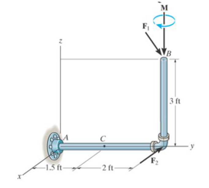
Probs. 7–42
Expert Solution & Answer
Want to see the full answer?
Check out a sample textbook solution
Students have asked these similar questions
Q: for the rigid pole and cross arm
assembly. determine the vector expression
for the moment of the 1.2KN tension about
point O and moment about z-axis. *
B 1.5 m
1.5 m
A
T = 1.2 kN
3 m
2 m
1.5 m
31
Mo= 0.998i +1.996j +0.995k, Mz= 0.665k
Mo= -2.89i -0.962k, Mz= -0.962k
Mo= 0.998i +0.996j +1.995k, Mz= -0.665k
A force of magnitude P = 166 N is applied to the stationary machine handle as shown. Write the force and moment reactions at O as
vectors. Neglect the weight of the handle assembly.
A
12
125 mm
165 mm
-y
Answers:
R = (
-162.37
i+
-0
j+
-34.51
k)N
M = (
i
-5694.15
i+ i
-2029.25
j+
i
26791.05
k) N-m
Determine the moment of the force about point O. Neglect the thickness of
the member. Assume F = 60 N. Sign convention applies for the answer
(positive is anti-clockwise).
F
-100 mm-
m - 1600
45° 200 mm
Answers:
(a) -13.5 Nm
(b) 13.5 Nm
(c) 12.0 Nm
(d) -12.0 Nm
-100 mm-
Chapter 7 Solutions
EP ENGR.MECH.-MOD.MASTERING ACCESS
Ch. 7 - Determine the normal force, shear force, and...Ch. 7 - Determine the normal force, shear force, and...Ch. 7 - Determine the normal force, shear force, and...Ch. 7 - Determine the normal force, shear force, and...Ch. 7 - Determine the normal force, shear force, and...Ch. 7 - Determine the normal force, shear force, and...Ch. 7 - Determine the shear force and moment at points C...Ch. 7 - The pliers are used to grip the tube at B. If a...Ch. 7 - Determine the distance a as a fraction of the...Ch. 7 - The cable will fail when subjected to a tension of...
Ch. 7 - Determine the distance a between the bearings in...Ch. 7 - The cantilevered rack is used to support each end...Ch. 7 - Rod AB is fixed to a smooth collar D, which slides...Ch. 7 - Prob. 22PCh. 7 - Determine the normal force, shear force, and...Ch. 7 - The distributed loading W = W0 sin , measured per...Ch. 7 - Solve Prob. 7-39 for = 120. Probs. 739/40Ch. 7 - Determine the x, y, z components of force and...Ch. 7 - Determine the x, y, z components of internal...Ch. 7 - Determine the shear and moment as a function of x,...Ch. 7 - Determine the shear and moment as a function of x,...Ch. 7 - Determine the shear and moment as a function of x,...Ch. 7 - Determine the shear and moment as a function of x,...Ch. 7 - Determine the shear and moment as a function of x,...Ch. 7 - Determine the shear and moment as a function of x,...Ch. 7 - Draw the shear and moment diagrams for the shaft...Ch. 7 - Draw the shear and moment diagrams for the beam...Ch. 7 - Draw the shear and moment diagrams for the beam...Ch. 7 - Draw the shear and moment diagrams for the...Ch. 7 - Draw the shear and moment diagrams of the beam (a)...Ch. 7 - If L = 9 m, the beam will fail when the maximum...Ch. 7 - Draw the shear and moment diagrams for the beam....Ch. 7 - Draw the shear and moment diagrams for the beam....Ch. 7 - The shaft is supported by a smooth thrust bearing...Ch. 7 - Draw the shear and moment diagrams for the beam....Ch. 7 - Prob. 58PCh. 7 - Prob. 59PCh. 7 - The shaft is supported by a smooth thrust bearing...Ch. 7 - Draw the shear and moment diagrams for the beam....Ch. 7 - Prob. 65PCh. 7 - Draw the shear and moment diagrams for the beam....Ch. 7 - Draw the shear and moment diagrams for the beam....Ch. 7 - Draw the shear and moment diagrams for the beam....Ch. 7 - Draw the shear and moment diagrams for the beam....Ch. 7 - Draw the shear and moment diagrams for the beam....Ch. 7 - Draw the shear and moment diagrams for the beam....Ch. 7 - Draw the shear and moment diagrams for the beam....Ch. 7 - Draw the shear and moment diagrams for the beam....Ch. 7 - Draw the shear and moment diagrams for the beam....Ch. 7 - Draw the shear and moment diagrams for the beam....Ch. 7 - Draw the shear and moment diagrams for the beam....Ch. 7 - Draw the shear and moment diagrams for the beam....Ch. 7 - Draw the shear and moment diagrams for the beam....Ch. 7 - The cable supports the three loads shown....Ch. 7 - Prob. 95PCh. 7 - Determine the tension in each segment of the cable...Ch. 7 - Prob. 97PCh. 7 - The cable supports the loading shown. Determine...Ch. 7 - The cable supports the three loads shown....Ch. 7 - The cable supports the three loads shown....Ch. 7 - Determine the maximum uniform loading w, measured...Ch. 7 - The cable is subjected to a uniform loading of w =...Ch. 7 - If x = 2 ft and the crate weighs 300 lb, which...Ch. 7 - If yB = 1.5 ft. determine the largest weight of...Ch. 7 - The cable supports a girder which weighs 850...Ch. 7 - If the pipe has a mass per unit length of 1500...Ch. 7 - Prob. 110PCh. 7 - The cable will break when the maximum tension...Ch. 7 - Prob. 2RPCh. 7 - Prob. 3RPCh. 7 - Prob. 4RPCh. 7 - Draw the shear and moment diagrams for the beam....Ch. 7 - A chain is suspended between points at the same...
Knowledge Booster


Learn more about
Need a deep-dive on the concept behind this application? Look no further. Learn more about this topic, mechanical-engineering and related others by exploring similar questions and additional content below.Similar questions
- Determine the moment of the force F about point 0, about point A, and about the line OB. Find the general results in terms of F, a, b, and c. Then answer with these numbers: F = 320 N, a = 230 mm, b = 655 mm, c = 420 mm. a B. Answers: Mo = ( i o i+ i -134.4 j+ i 0 k) N-m MA = (0 i+ i 134.4 i o k) N-m MOB = ( i i+ i 126.87 j+ k) N-marrow_forward7. The pipe assembly is subjected to the action of a wrench at B and a couple at A. Simplify this system to a resultant wrench and specify the location of the wrench along the axis of pipe CD, measured from point C. Set F=40N. 0.6 m 41 -0.8 m (60k) N 0.25 m {–40i} N B 0.25 m -Fi 0.3 m 0.3 m 0.7 m- VI-60k) N Fi 0.5 m D yarrow_forwardThe bent rod is supported at points A, B and C by smooth journal bearings, and is subjected to force F. If dimensions a = 2.3 m, b = 1.5 m, c = 0.6 m, and d = 2.5 m, and the force F is {-2i + 9j - 3k} kN, determine the magnitude of the moment (in kN⋅m) caused by force F about point A. Answer must include 2 places after the decimal point.arrow_forward
- The 50-N force P is applied perpendicular to the portion BC of the bent bar. Determine the monments of P about point B and about point A. As shown in the figure 1 P= 50 N C 2 m 46 2 m Figure 1arrow_forwardAforce of magnitude P = 166 N is applied to the stationary machine handle as shown. Write the force and moment reactions at O as vectors. Neglect the weight of the handle assembly. A P 12° 125 mm 165 mm -y Answers: R = ( -162.37 i+ -0 j+ -34.51 k)N M = ( i i+ i j+ i k) N-marrow_forwardThe bar shown in the following figure is subject to a force of intensity of 60N in the sense of C to B. Mark the alternative that correctly presents the moment vector created by this force in relation to the support at point A. Choose the right answer: a) M = (120,-160,100) b) M = (160,-80,160) c) M = (160,-120,100) d) M = (-120,-60,120) e) M = (-160,-80,160)arrow_forward
- Determine the maximum moment (k-ft) at the given structure. Support A is fixed, joint B is a pin and support C is roller. 20 k 0.5 k/ft B 8 ft 6 ft 6 ftarrow_forwardQ1\ The 50-N force P is applied perpendicular to the portion BC of the bent bar. Determine the moments of P about point B and about point A. As shown in the figure 1 P= 50 N 2m 2 m Figure Iarrow_forward2 of 4 -/8 The 35-N force P is applied perpendicular to the portion BC of the bent bar. Determine the moment of P about point B and about point A. Moments are positive if counterclockwise, negative if clockwise. P = 35 N 2.0 m 48° B 2.0 m A Answers: MB = N•m MA = %3Darrow_forward
- Determine the reactive forces and moments at the point O and point A 6 kN/m 15 kN 500 kN m A 7.5 m 4.5 marrow_forwardQ1\ The 50-N force P is applied perpendicular to the portion BC of the bent bar. Determine the moments of P about point B and about point A. As shown in the figure 1 P= 50 N 2 m 46 2 marrow_forward8:29 46 ll 69%i MENG250 - Pract... / 4-55. Determine the moment of the force F about an axis extending between A and C. Express the result as a Cartesian vector. 4 ft 3 ft. 2 ft F- (4i + 12j - 3k) Ib 7/10arrow_forward
arrow_back_ios
SEE MORE QUESTIONS
arrow_forward_ios
Recommended textbooks for you
 Elements Of ElectromagneticsMechanical EngineeringISBN:9780190698614Author:Sadiku, Matthew N. O.Publisher:Oxford University Press
 Mechanics of Materials (10th Edition)Mechanical EngineeringISBN:9780134319650Author:Russell C. HibbelerPublisher:PEARSON
 Thermodynamics: An Engineering ApproachMechanical EngineeringISBN:9781259822674Author:Yunus A. Cengel Dr., Michael A. BolesPublisher:McGraw-Hill Education
 Control Systems EngineeringMechanical EngineeringISBN:9781118170519Author:Norman S. NisePublisher:WILEY
 Mechanics of Materials (MindTap Course List)Mechanical EngineeringISBN:9781337093347Author:Barry J. Goodno, James M. GerePublisher:Cengage Learning
 Engineering Mechanics: StaticsMechanical EngineeringISBN:9781118807330Author:James L. Meriam, L. G. Kraige, J. N. BoltonPublisher:WILEY
Elements Of Electromagnetics
Mechanical Engineering
ISBN:9780190698614
Author:Sadiku, Matthew N. O.
Publisher:Oxford University Press
Mechanics of Materials (10th Edition)
Mechanical Engineering
ISBN:9780134319650
Author:Russell C. Hibbeler
Publisher:PEARSON
Thermodynamics: An Engineering Approach
Mechanical Engineering
ISBN:9781259822674
Author:Yunus A. Cengel Dr., Michael A. Boles
Publisher:McGraw-Hill Education
Control Systems Engineering
Mechanical Engineering
ISBN:9781118170519
Author:Norman S. Nise
Publisher:WILEY
Mechanics of Materials (MindTap Course List)
Mechanical Engineering
ISBN:9781337093347
Author:Barry J. Goodno, James M. Gere
Publisher:Cengage Learning
Engineering Mechanics: Statics
Mechanical Engineering
ISBN:9781118807330
Author:James L. Meriam, L. G. Kraige, J. N. Bolton
Publisher:WILEY
Types Of loads - Engineering Mechanics | Abhishek Explained; Author: Prime Course;https://www.youtube.com/watch?v=4JVoL9wb5yM;License: Standard YouTube License, CC-BY