
EP ENGR.MECH.-MOD.MASTERING ACCESS
15th Edition
ISBN: 9780134867267
Author: HIBBELER
Publisher: PEARSON CO
expand_more
expand_more
format_list_bulleted
Videos
Textbook Question
Chapter 7, Problem 5P
The pliers are used to grip the tube at B. If a force of 20 lb is applied to the handles, determine the internal shear force and moment a point C. Assume the jaws of the pliers exert only normal forces on the tube.
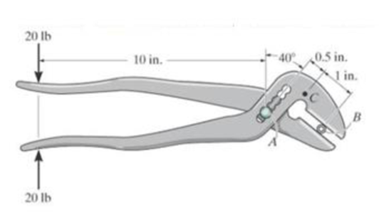
Prob. 7-5
Expert Solution & Answer
Want to see the full answer?
Check out a sample textbook solution
Students have asked these similar questions
•7-13. Determine the internal normal force, shear force,
and moment at point D of the two-member frame.
7-14. Determine the internal normal force, shear force,
and moment at point E of the two-member frame.
250 N/m
2 m
15 m
300 N/m
Probs. 7-13/14
*4-20. The tongs are used to grip the ends of the drilling
pipe P. If a torque (moment) of Mp = 800 lb ft is needed
at P to turn the pipe, determine the cable force F that must
be applied to the tongs. Set 0 = 30°.
%3D
F
6 in.
OR Mp
43 in.-
Probs, 4-19/20
*7-36. Determine the normal force, shear force, and moment acting at points B and C on the
curved member.
Problem 7-36
B
2 ft
45°
30°
3
500 lb
Chapter 7 Solutions
EP ENGR.MECH.-MOD.MASTERING ACCESS
Ch. 7 - Determine the normal force, shear force, and...Ch. 7 - Determine the normal force, shear force, and...Ch. 7 - Determine the normal force, shear force, and...Ch. 7 - Determine the normal force, shear force, and...Ch. 7 - Determine the normal force, shear force, and...Ch. 7 - Determine the normal force, shear force, and...Ch. 7 - Determine the shear force and moment at points C...Ch. 7 - The pliers are used to grip the tube at B. If a...Ch. 7 - Determine the distance a as a fraction of the...Ch. 7 - The cable will fail when subjected to a tension of...
Ch. 7 - Determine the distance a between the bearings in...Ch. 7 - The cantilevered rack is used to support each end...Ch. 7 - Rod AB is fixed to a smooth collar D, which slides...Ch. 7 - Prob. 22PCh. 7 - Determine the normal force, shear force, and...Ch. 7 - The distributed loading W = W0 sin , measured per...Ch. 7 - Solve Prob. 7-39 for = 120. Probs. 739/40Ch. 7 - Determine the x, y, z components of force and...Ch. 7 - Determine the x, y, z components of internal...Ch. 7 - Determine the shear and moment as a function of x,...Ch. 7 - Determine the shear and moment as a function of x,...Ch. 7 - Determine the shear and moment as a function of x,...Ch. 7 - Determine the shear and moment as a function of x,...Ch. 7 - Determine the shear and moment as a function of x,...Ch. 7 - Determine the shear and moment as a function of x,...Ch. 7 - Draw the shear and moment diagrams for the shaft...Ch. 7 - Draw the shear and moment diagrams for the beam...Ch. 7 - Draw the shear and moment diagrams for the beam...Ch. 7 - Draw the shear and moment diagrams for the...Ch. 7 - Draw the shear and moment diagrams of the beam (a)...Ch. 7 - If L = 9 m, the beam will fail when the maximum...Ch. 7 - Draw the shear and moment diagrams for the beam....Ch. 7 - Draw the shear and moment diagrams for the beam....Ch. 7 - The shaft is supported by a smooth thrust bearing...Ch. 7 - Draw the shear and moment diagrams for the beam....Ch. 7 - Prob. 58PCh. 7 - Prob. 59PCh. 7 - The shaft is supported by a smooth thrust bearing...Ch. 7 - Draw the shear and moment diagrams for the beam....Ch. 7 - Prob. 65PCh. 7 - Draw the shear and moment diagrams for the beam....Ch. 7 - Draw the shear and moment diagrams for the beam....Ch. 7 - Draw the shear and moment diagrams for the beam....Ch. 7 - Draw the shear and moment diagrams for the beam....Ch. 7 - Draw the shear and moment diagrams for the beam....Ch. 7 - Draw the shear and moment diagrams for the beam....Ch. 7 - Draw the shear and moment diagrams for the beam....Ch. 7 - Draw the shear and moment diagrams for the beam....Ch. 7 - Draw the shear and moment diagrams for the beam....Ch. 7 - Draw the shear and moment diagrams for the beam....Ch. 7 - Draw the shear and moment diagrams for the beam....Ch. 7 - Draw the shear and moment diagrams for the beam....Ch. 7 - Draw the shear and moment diagrams for the beam....Ch. 7 - The cable supports the three loads shown....Ch. 7 - Prob. 95PCh. 7 - Determine the tension in each segment of the cable...Ch. 7 - Prob. 97PCh. 7 - The cable supports the loading shown. Determine...Ch. 7 - The cable supports the three loads shown....Ch. 7 - The cable supports the three loads shown....Ch. 7 - Determine the maximum uniform loading w, measured...Ch. 7 - The cable is subjected to a uniform loading of w =...Ch. 7 - If x = 2 ft and the crate weighs 300 lb, which...Ch. 7 - If yB = 1.5 ft. determine the largest weight of...Ch. 7 - The cable supports a girder which weighs 850...Ch. 7 - If the pipe has a mass per unit length of 1500...Ch. 7 - Prob. 110PCh. 7 - The cable will break when the maximum tension...Ch. 7 - Prob. 2RPCh. 7 - Prob. 3RPCh. 7 - Prob. 4RPCh. 7 - Draw the shear and moment diagrams for the beam....Ch. 7 - A chain is suspended between points at the same...
Additional Engineering Textbook Solutions
Find more solutions based on key concepts
Compute the hydraulic radius for a circular drain pipe running half full if its inside diameter is 300 mm.
Applied Fluid Mechanics (7th Edition)
Find the change in length of side AB.
Mechanics of Materials, 7th Edition
3.3 It is known that a vertical force of 200 lb is required to remove the nail at C from the board. As the nail...
Vector Mechanics for Engineers: Statics
What is the importance of modeling in engineering? How are the mathematical models for engineering processes pr...
HEAT+MASS TRANSFER:FUND.+APPL.
What is the importance of modeling in engineering? How are the mathematical models for engineering processes pr...
Heat and Mass Transfer: Fundamentals and Applications
A 20-lb force is applied to the control rod AB as shown. Knowing that the length of the rod is 9 in. and that t...
Statics and Mechanics of Materials
Knowledge Booster


Learn more about
Need a deep-dive on the concept behind this application? Look no further. Learn more about this topic, mechanical-engineering and related others by exploring similar questions and additional content below.Similar questions
- 7-11. The shaft is supported by a journal bearing at A and a thrust bearing at B. Determine the normal force, shear force, and moment at a section passing through (a) point C, which is just to the right of the bearing at A, and (b) point D, which is just to the left of the 3000-lb force. 3000 lb 2500 lb 75 lb/ft B 6 ft- -12 ft- 2 ftarrow_forwardR3-1. The boom has a length of 9 m, a weight of 4 kN, and mass center at G. If the maximum moment that can be developed by a motor at A is M - 30 kN - m, determine the maximum load w, having a mass center at G', that can be lifted. 4 kN Sm 30 0.6 marrow_forwardP5-3. then draw the free-body diagrams of each member of the identify any two-force members, and frame. 800 N 200 N/m 6 m- -2 m m-arrow_forward
- 6-1. Draw the shear and moment diagrams for the shaft. The bearings at A and B exert only vertical reactions on the shaft. B -800 mm 250 mm 24 kNarrow_forwardDetermine the normal force, shear force, and moment at points D and E of the two-member frame. Note that while BC is pinned at both ends, it is not a 2-force member. 2 kN/m A 1.5 m D -1.5 m 1.5 m E 1.5 m B 1.5 kN/marrow_forward5-10. Determine the components of the support reactions at the fixed support A on the cantilevered beam. A 6 kN -1.5 m 1.5 m- Prob. 5-10 30° 1.5 m 30° 4 kNarrow_forward
- 6-127. Determine the clamping force exerted on the smooth pipe at B if a force of 20 lb is applied to the handles of the pliers. The pliers are pinned together at A. 20 lb 20 lb 10 in. 40° 1.5 in. 0.5 in. Barrow_forwardP6-1. use the element shown and specify i, y, and dA.arrow_forward11-17. Draw the sheur and moment diagrams for the rod. It is supported by a pin at A and a smooth plate at B. The plate slides within the groove and so it cannot support a vertical force, although it can support a moment. 15 KN -2 m-arrow_forward
- 6-40. The compound beam is fixed supported at C and supported by rockers at A and B. If there are hinges (pins) at D and E, determine the components of reaction at the supports. Neglect the thickness of the beam. 900 lb 400 lb A 0 2 ft 300 lb B FRESSPOR -6 ft4 ft 4 ft D 4 ft- 2 ft Prob. 6-40 E 650 lb 13/12 2 ft C -8 ft- 4arrow_forward*4-12. The rigid metal strip of negligible weight is used as part of an electromagnetic switch. If the stiffness of the springs at A and B is k -5 N/m and the strip is originally horizontal when the springs are unstretched, determine the smallest force Fneeded to close the contact gap at C. -50 mm -50 mm 10 mmarrow_forward4-69. The pipe assembly is secured on the wall by the two brackets. If the frictional force of both brackets can resist a maximum moment of 150 lb ft, determine the largest weight of the flowerpot that can be supported by the assembly. 60⁰⁰ 4 10 3 ftarrow_forward
arrow_back_ios
SEE MORE QUESTIONS
arrow_forward_ios
Recommended textbooks for you
 Elements Of ElectromagneticsMechanical EngineeringISBN:9780190698614Author:Sadiku, Matthew N. O.Publisher:Oxford University Press
 Mechanics of Materials (10th Edition)Mechanical EngineeringISBN:9780134319650Author:Russell C. HibbelerPublisher:PEARSON
 Thermodynamics: An Engineering ApproachMechanical EngineeringISBN:9781259822674Author:Yunus A. Cengel Dr., Michael A. BolesPublisher:McGraw-Hill Education
 Control Systems EngineeringMechanical EngineeringISBN:9781118170519Author:Norman S. NisePublisher:WILEY
 Mechanics of Materials (MindTap Course List)Mechanical EngineeringISBN:9781337093347Author:Barry J. Goodno, James M. GerePublisher:Cengage Learning
 Engineering Mechanics: StaticsMechanical EngineeringISBN:9781118807330Author:James L. Meriam, L. G. Kraige, J. N. BoltonPublisher:WILEY
Elements Of Electromagnetics
Mechanical Engineering
ISBN:9780190698614
Author:Sadiku, Matthew N. O.
Publisher:Oxford University Press
Mechanics of Materials (10th Edition)
Mechanical Engineering
ISBN:9780134319650
Author:Russell C. Hibbeler
Publisher:PEARSON
Thermodynamics: An Engineering Approach
Mechanical Engineering
ISBN:9781259822674
Author:Yunus A. Cengel Dr., Michael A. Boles
Publisher:McGraw-Hill Education
Control Systems Engineering
Mechanical Engineering
ISBN:9781118170519
Author:Norman S. Nise
Publisher:WILEY
Mechanics of Materials (MindTap Course List)
Mechanical Engineering
ISBN:9781337093347
Author:Barry J. Goodno, James M. Gere
Publisher:Cengage Learning
Engineering Mechanics: Statics
Mechanical Engineering
ISBN:9781118807330
Author:James L. Meriam, L. G. Kraige, J. N. Bolton
Publisher:WILEY
Mechanics of Materials Lecture: Beam Design; Author: UWMC Engineering;https://www.youtube.com/watch?v=-wVs5pvQPm4;License: Standard Youtube License