EP ENGR.MECH.-MOD.MASTERING ACCESS
15th Edition
ISBN: 9780134867267
Author: HIBBELER
Publisher: PEARSON CO
expand_more
expand_more
format_list_bulleted
Concept explainers
Videos
Textbook Question
Chapter 7, Problem 40P
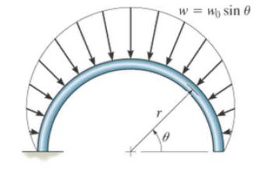
Solve Prob. 7-39 for θ = 120°.
Probs. 7–39/40
Expert Solution & Answer
Want to see the full answer?
Check out a sample textbook solution
Students have asked these similar questions
7-9. Determine the resultant internal loading on the cross
section through point D of the pliers.
20 N
20 N
120 mm
80 mm
**************
poseen
30°
D
Probs. 7-8/9
A
40 mm
15 mm
B
7-19. The shaft is supported at its ends by two bearings
A and B and is subjected to the forces applied to the pulleys
fixed to the shaft. Determine the resultant internal loadings
acting on the cross section at point D.The 400-N forces act in
the -z direction and the 200-N and 80-N forces act in the +y
direction. The journal bearings at A and B exert only y and z
components of force on the shaft.
400 mim
150 mm
150 mm
200 mm
200 mm
300 mm
80N
80N
200 N
200 N
P400 N
400 N
7-18. The shaft is supported at its ends by two bearings
A and B and is subjected to the forces applied to the pulleys
fixed to the shaft. Determine the resultant internal loadings
acting on the cross section at point C. The 400-N forces act
in the -z direction and the 200-N and 80-N forces act in the
+y direction. The journal bearings at A and B exert only y
and z components of force on the shaft.
400 mm
150 mm
150 mm
200 mm
200 mm
300 m
SON
S0N
200 N
200 N
P400 N
400 N
Chapter 7 Solutions
EP ENGR.MECH.-MOD.MASTERING ACCESS
Ch. 7 - Determine the normal force, shear force, and...Ch. 7 - Determine the normal force, shear force, and...Ch. 7 - Determine the normal force, shear force, and...Ch. 7 - Determine the normal force, shear force, and...Ch. 7 - Determine the normal force, shear force, and...Ch. 7 - Determine the normal force, shear force, and...Ch. 7 - Determine the shear force and moment at points C...Ch. 7 - The pliers are used to grip the tube at B. If a...Ch. 7 - Determine the distance a as a fraction of the...Ch. 7 - The cable will fail when subjected to a tension of...
Ch. 7 - Determine the distance a between the bearings in...Ch. 7 - The cantilevered rack is used to support each end...Ch. 7 - Rod AB is fixed to a smooth collar D, which slides...Ch. 7 - Prob. 22PCh. 7 - Determine the normal force, shear force, and...Ch. 7 - The distributed loading W = W0 sin , measured per...Ch. 7 - Solve Prob. 7-39 for = 120. Probs. 739/40Ch. 7 - Determine the x, y, z components of force and...Ch. 7 - Determine the x, y, z components of internal...Ch. 7 - Determine the shear and moment as a function of x,...Ch. 7 - Determine the shear and moment as a function of x,...Ch. 7 - Determine the shear and moment as a function of x,...Ch. 7 - Determine the shear and moment as a function of x,...Ch. 7 - Determine the shear and moment as a function of x,...Ch. 7 - Determine the shear and moment as a function of x,...Ch. 7 - Draw the shear and moment diagrams for the shaft...Ch. 7 - Draw the shear and moment diagrams for the beam...Ch. 7 - Draw the shear and moment diagrams for the beam...Ch. 7 - Draw the shear and moment diagrams for the...Ch. 7 - Draw the shear and moment diagrams of the beam (a)...Ch. 7 - If L = 9 m, the beam will fail when the maximum...Ch. 7 - Draw the shear and moment diagrams for the beam....Ch. 7 - Draw the shear and moment diagrams for the beam....Ch. 7 - The shaft is supported by a smooth thrust bearing...Ch. 7 - Draw the shear and moment diagrams for the beam....Ch. 7 - Prob. 58PCh. 7 - Prob. 59PCh. 7 - The shaft is supported by a smooth thrust bearing...Ch. 7 - Draw the shear and moment diagrams for the beam....Ch. 7 - Prob. 65PCh. 7 - Draw the shear and moment diagrams for the beam....Ch. 7 - Draw the shear and moment diagrams for the beam....Ch. 7 - Draw the shear and moment diagrams for the beam....Ch. 7 - Draw the shear and moment diagrams for the beam....Ch. 7 - Draw the shear and moment diagrams for the beam....Ch. 7 - Draw the shear and moment diagrams for the beam....Ch. 7 - Draw the shear and moment diagrams for the beam....Ch. 7 - Draw the shear and moment diagrams for the beam....Ch. 7 - Draw the shear and moment diagrams for the beam....Ch. 7 - Draw the shear and moment diagrams for the beam....Ch. 7 - Draw the shear and moment diagrams for the beam....Ch. 7 - Draw the shear and moment diagrams for the beam....Ch. 7 - Draw the shear and moment diagrams for the beam....Ch. 7 - The cable supports the three loads shown....Ch. 7 - Prob. 95PCh. 7 - Determine the tension in each segment of the cable...Ch. 7 - Prob. 97PCh. 7 - The cable supports the loading shown. Determine...Ch. 7 - The cable supports the three loads shown....Ch. 7 - The cable supports the three loads shown....Ch. 7 - Determine the maximum uniform loading w, measured...Ch. 7 - The cable is subjected to a uniform loading of w =...Ch. 7 - If x = 2 ft and the crate weighs 300 lb, which...Ch. 7 - If yB = 1.5 ft. determine the largest weight of...Ch. 7 - The cable supports a girder which weighs 850...Ch. 7 - If the pipe has a mass per unit length of 1500...Ch. 7 - Prob. 110PCh. 7 - The cable will break when the maximum tension...Ch. 7 - Prob. 2RPCh. 7 - Prob. 3RPCh. 7 - Prob. 4RPCh. 7 - Draw the shear and moment diagrams for the beam....Ch. 7 - A chain is suspended between points at the same...
Knowledge Booster


Learn more about
Need a deep-dive on the concept behind this application? Look no further. Learn more about this topic, mechanical-engineering and related others by exploring similar questions and additional content below.Similar questions
- Solve Prob. 7.29 if =0.arrow_forward7-18. The shaft is supported at its ends by two bearings A and B and is subjected to the forces applied to the pulleys fixed to the shaft. Determine the resultant internal loadings acting on the cross section at point C. The 400-N forces act in the -z direction and the 200-N and 80-N forces act in the +y direction. The journal bearings at A and B exert only y and z components of force on the shaft. X A 200 mm 300 mm 200 mm 400 N 150 mm 150 mm 400 N D 400 mm 200 N Prob. 7-18 B 200 N Z 80 N 80 N yarrow_forward3/15 Find the angle of tilt e with the horizontal so that the contact force at B will be one-half that at A for the smooth cylinder. 45 45arrow_forward
- 7-15. The force F- 400 N acts on the gear tooth. Determine the resultant internal loadings on the root of the tooth, i.e., at the centroid point A of section a-a. F- 400 N 30 5.75 mm 4 mmarrow_forward8:29 46 ll 69%i MENG250 - Pract... / 4-55. Determine the moment of the force F about an axis extending between A and C. Express the result as a Cartesian vector. 4 ft 3 ft. 2 ft F- (4i + 12j - 3k) Ib 7/10arrow_forward6-72 Determine the resultant force at pins A, B. and C on the three-member frame! Hint: use segments AC and BC. Then, using the two segments, develop equations in terms of Cx and Cy. Find Cx and Cy. Then plug back in to the other equations to find the rest of the unknowns. 200 N/m 2 m 800 N 2 marrow_forward
- Determine the moment of the force about point O. Neglect the thickness of the member. Assume F = 60 N. Sign convention applies for the answer (positive is anti-clockwise). F -100 mm- m - 1600 45° 200 mm Answers: (a) -13.5 Nm (b) 13.5 Nm (c) 12.0 Nm (d) -12.0 Nm -100 mm-arrow_forward7-11. The shaft is supported by a journal bearing at A and a thrust bearing at B. Determine the normal force, shear force, and moment at a section passing through (a) point C, which is just to the right of the bearing at A, and (b) point D, which is just to the left of the 3000-lb force. 3000 lb 2500 lb 75 lb/ft B 6 ft- -12 ft- 2 ftarrow_forward5-107 Determine the resultant R of the system of dis- tributed loads on the beam of Fig. P5-107 and locate its line of action with respect to the left support of the beam. y w = 200 Va Ibvft w = 400 Ib/ft 4 ft 4 ft 4 ftarrow_forward
- The beam of negligible weight is supported horizontally by two springs. If the beam is horizontal and the springs are unstretched when the load is removed, determine the angle of tilt of the beam when the load is applied. Take x = 659 N/m, y = 1.5 kN/m, and z = 1.6 kN/m.arrow_forwardR16-7 If the temperature of the 75-mm-diameter post CD is increased by 60C, determine the force developed in the post. The post and the beam are made of A-36 steel, and the moment of inertia of the beam is I = 255(10)mm.arrow_forward*7-36. Determine the normal force, shear force, and moment acting at points B and C on the curved member. Problem 7-36 B 2 ft 45° 30° 3 500 lbarrow_forward
arrow_back_ios
SEE MORE QUESTIONS
arrow_forward_ios
Recommended textbooks for you
 International Edition---engineering Mechanics: St...Mechanical EngineeringISBN:9781305501607Author:Andrew Pytel And Jaan KiusalaasPublisher:CENGAGE L
International Edition---engineering Mechanics: St...
Mechanical Engineering
ISBN:9781305501607
Author:Andrew Pytel And Jaan Kiusalaas
Publisher:CENGAGE L
Solids: Lesson 53 - Slope and Deflection of Beams Intro; Author: Jeff Hanson;https://www.youtube.com/watch?v=I7lTq68JRmY;License: Standard YouTube License, CC-BY