
Concept explainers
Videos
(a)
Find the energy stored in the element at time
(a)
Answer to Problem 69E
The energy stored in the element at time
Explanation of Solution
Formula used:
Write a general expression to calculate the energy stored in an capacitor.
Here,
Given data:
Refer to Figure 7.83 in the textbook.
The value of initial voltage across the capacitor
Calculation:
Substitute
Substitute
Simplify the above equation to find
Conclusion:
Thus, the energy stored in the element at time
(b)
Explain whether the energy stored in the capacitor remains same for time
(b)
Answer to Problem 69E
No, the energy is not same in the capacitor for time
Explanation of Solution
Refer to Figure 7.83, it shows an
Due to the presence of resistor in a circuit, there is a voltage drop across the resistor which reduces the voltage across the capacitor. Therefore, the resistor slowly dissipate the energy stored in a capacitor for time
Conclusion:
Thus, the energy is not same in the capacitor for time
(c)
Determine the value of
(c)
Answer to Problem 69E
The value of
Explanation of Solution
Calculation:
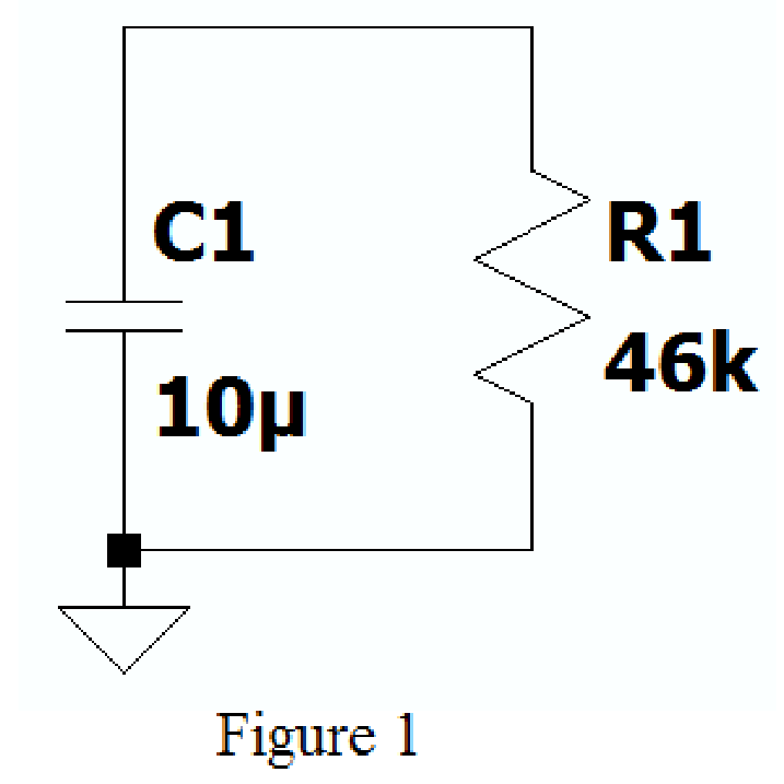
Create the new schematic in LTspice with series connected resistor and inductor of given circuit as shown in Figure 1.
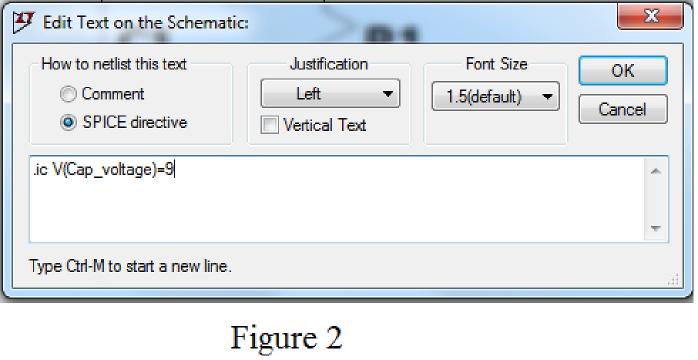
Using SPICE Directive mention the command .ic V(Cap_voltage)=9 as shown in Figure 2.
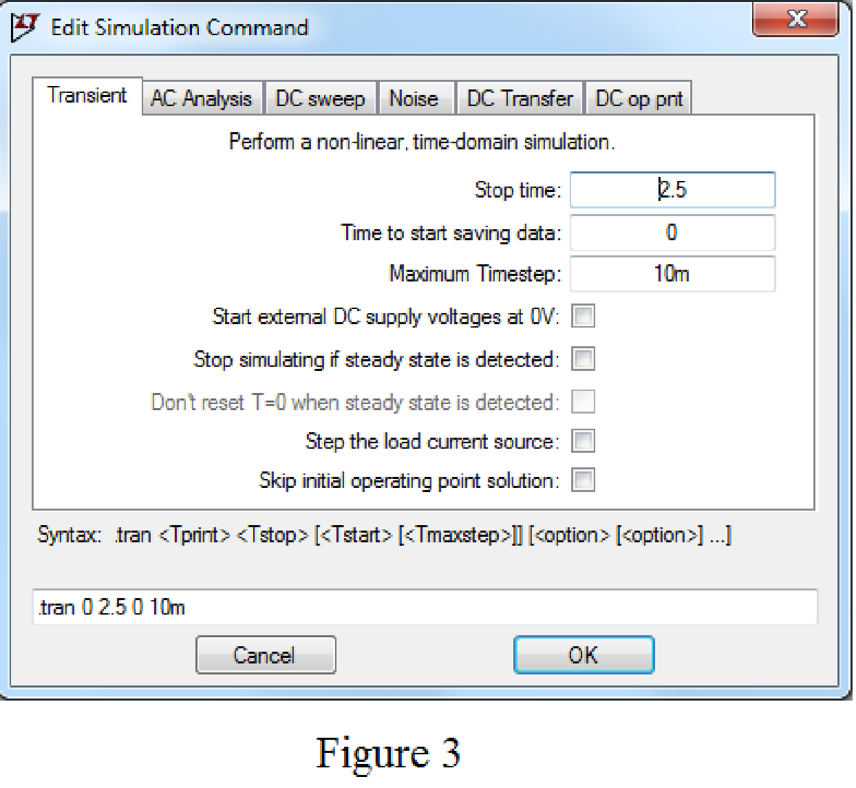
Enter the stop time as 2.5s, time to start saving data as 0, and maximum Timestep as 10ms in Edit simulation Cmd as shown in Figure 3. Use label net option and mention Cap_voltage.
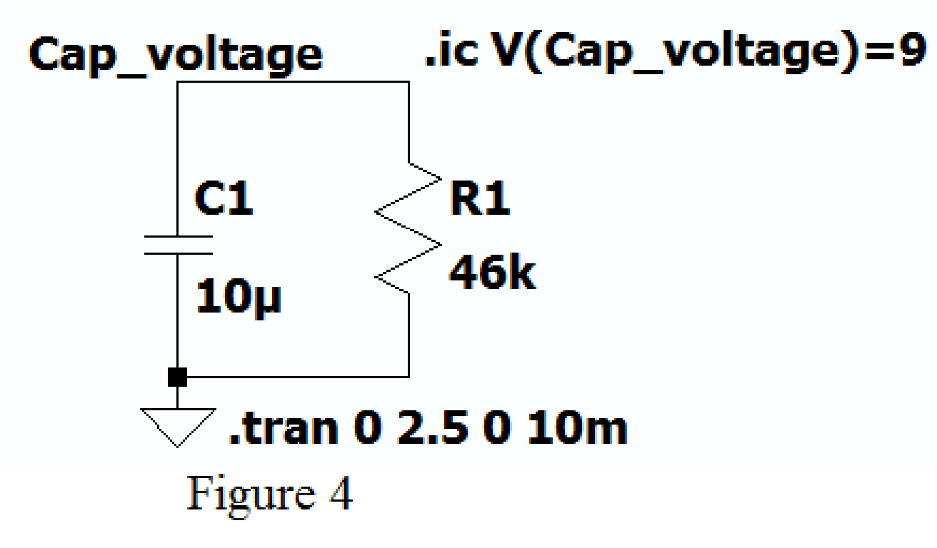
After adding the Spice directives the circuit shows as in Figure 4.
Now run the simulation and place the probe at the node of capacitor, the plot of the voltage across the capacitor with respect to time is shown as shown in Figure 5.
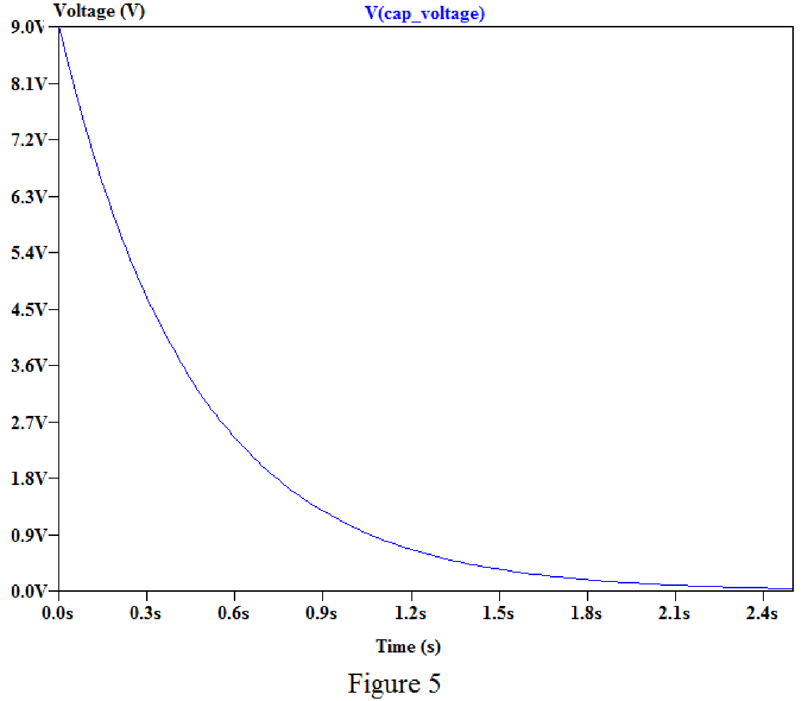
By placing the cursor on the graph, we obtain the current values for different time as shown in below.
For time
For time
For time
For time
Conclusion:
Thus, the value of
(d)
Find the fraction of initial energy remains in the capacitor at time
(d)
Answer to Problem 69E
The fraction of initial energy remains in the capacitor at time
Explanation of Solution
Calculation:
Refer to part (b), the value of voltage at time
Substitute
Substitute
Simplify the above equation to find
Substitute
Substitute
Simplify the above equation to find
The fraction of initial energy remains stored in the capacitor at time
Substitute
The fraction of initial energy remains stored in the capacitor at time
Substitute
Conclusion:
Thus, the fraction of initial energy remains in the capacitor at time
Want to see more full solutions like this?
Chapter 7 Solutions
Loose Leaf for Engineering Circuit Analysis Format: Loose-leaf


- 2. 7.22 The switch in the circuit has been in the left positionfor a long time. At t=0 it moves to the right position and stays there. 1. a) Write the expression for the capacitor voltage, v(t), for t≥0arrow_forwardTwo capacitors, of capacitance 3µF and 5µF, are connected as shown to batteries A and B which have EMF 4 V and 12 V respectively. What is the energy stored in each of the capacitors? Calculate also the stored energy in each capacitor when the terminals of battery A are reversed, and when the battery B is disconnected, and the points X and Y are connected together.arrow_forwardThe current in and the voltage across a 5 H inductor are known to be zero for t≤0. The voltage across the inductor is given by the graph shown for t≥0. 1. Derive the expression for the current as a function of time in the intervals 0≤t≤1 s, 1 s≤t≤3 s, 3 s≤t≤5 s, 5 s≤t≤6 s, and 6 s≤t<∞. 2. For t>0, what is the current in the inductor when the voltage is zero? 3. Sketch i versus t for 0≤t<∞.arrow_forward
- The voltage pulse applied to the 100 mH inductor shown is 0 for t<0 and is given by the expression v(t)=20te−10t V for t>0. Also assume i=0 for t≤0. Sketch the current as a function of time.arrow_forwardThe current flowing through a 10-μF capacitor having terminals labeled a and b is i ab =0.3 exp( −2000t ) Afor t≥0 Given that v ab ( 0 )=0, find an expression for v ab (t) for t≥0. Then,find the energy stored in the capacitor for t=∞..arrow_forwardA 100µF capacitor is connected in series with a 150volt voltmeter that has a resistance of 1,000 ohms per volt. Calculate the reading of the voltmeter at the instant when t equals the time constant following the closing if the switch that impresses 120volts on the circuit.arrow_forward
- Consider the circuit. The switch has been closed for a long time before opening at t=0s. Give the expression for the capacitor current for t≥0 and the total dissipated energy (in μJ) in the 10KΩ resistor 5ms after the switch has been opened.arrow_forwardThe voltage across a 2µF capacitor is shown in Fig. Determine the waveformfor the capacitor current (a) Find mathematical expression of v(t) for 0 ≤ t ≤ 2 (b) Find mathematical expression of v(t) for 2 ≤ t ≤ 6arrow_forwardThe voltage pulse applied to the 100 mH inductor shown is 0 for t<0. and is given by the expression v(t)=20te−10t V for t>0. Also assume i=0 for t≤0. Sketch the voltage as a function of time.arrow_forward
- * Determine the charge stored on a 2.2 µF capacitor if the capacitor’s voltage is 5 V. *In some integrated circuits, the insulator or dielectric is silicon dioxide, which has a relative permittivity of 4. If a square capacitor measuring 10 µm on edge, has a capacitance of 100 fF, what is the separation distance between the capacitor’s plates, in µm?arrow_forwardFor the circuit shown, calculate 1. the initial energy stored in the capacitors; 2. the final energy stored in the capacitors; 3. the total energy delivered to the black box; 4. the percentage of the initial energy stored that is delivered to the black box; and 5. the time, in milliseconds, it takes to deliver 7.5 mJ to the black box.arrow_forwardIn the circuit below, the switch is closed at t=0 s. It is known that the voltage across the capacitor at t=0.2 s is Vc( t = 0.2 ) = 10.31 V. In this case, what will be the voltage Vc( t = 0.1 ) of the capacitor at t=0.1 s? Calculate.arrow_forward
 Introductory Circuit Analysis (13th Edition)Electrical EngineeringISBN:9780133923605Author:Robert L. BoylestadPublisher:PEARSON
 Delmar's Standard Textbook Of ElectricityElectrical EngineeringISBN:9781337900348Author:Stephen L. HermanPublisher:Cengage Learning
 Programmable Logic ControllersElectrical EngineeringISBN:9780073373843Author:Frank D. PetruzellaPublisher:McGraw-Hill Education
 Fundamentals of Electric CircuitsElectrical EngineeringISBN:9780078028229Author:Charles K Alexander, Matthew SadikuPublisher:McGraw-Hill Education
 Electric Circuits. (11th Edition)Electrical EngineeringISBN:9780134746968Author:James W. Nilsson, Susan RiedelPublisher:PEARSON
 Engineering ElectromagneticsElectrical EngineeringISBN:9780078028151Author:Hayt, William H. (william Hart), Jr, BUCK, John A.Publisher:Mcgraw-hill Education,