
Loose Leaf for Engineering Circuit Analysis Format: Loose-leaf
9th Edition
ISBN: 9781259989452
Author: Hayt
Publisher: Mcgraw Hill Publishers
expand_more
expand_more
format_list_bulleted
Concept explainers
Videos
Textbook Question
Chapter 7, Problem 71E
For the circuit of Fig. 7.28, (a) sketch vout over the range of 0 ≤ t ≤ 5 ms if Rf = 1 kΩ, C1 = 1 nF, and vs is a 1 kHz sinusoidal source having a peak voltage of 2 V. (b) Using ±15 V supplies for the op amp, perform an appropriate transient simulation and plot vout.
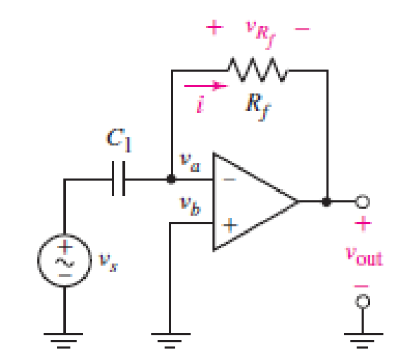
■ FIGURE 7.28 An ideal op amp connected as a differentiator.
Expert Solution & Answer
Want to see the full answer?
Check out a sample textbook solution
Students have asked these similar questions
In response to a change introduced by a switch at t = 0,
the current flowing through a 100 μF capacitor, defined in
accordance with the passive sign convention, was observed to be
i(t) = −0.4e−0.5t mA (for t > 0).
If the final energy stored in the capacitor (at t = ∞) is 0.2 mJ,
determine υ(t) for t ≥ 0.
The switch in the circuit shown in Fig. 7.6 has been closed for a long timebefore it is opened at t=0. Find 4. the percentage of the total energy stored in the 2 H inductor that isdissipated in the 10 Ω resistor.
The initial condition current of the inductance is given as iL(0)=1A. circuitBy analyzing the domain of s, we can find the intrinsic solution, forced solution, and exact solution of the current iL(t).find.Element values R1=R2=R3=1Ω, e(t)=Cos 3t Volts,It is L=β H.
α=7,β=4
Chapter 7 Solutions
Loose Leaf for Engineering Circuit Analysis Format: Loose-leaf
Ch. 7.1 - Determine the current flowing through a 5 mF...Ch. 7.1 - Prob. 2PCh. 7.1 - Prob. 3PCh. 7.2 - 7.4 The current through a 200 mH inductor is shown...Ch. 7.2 - The current waveform of Fig. 7.14a has equal rise...Ch. 7.2 - Prob. 6PCh. 7.2 - Let L = 25 mH for the inductor of Fig. 7.10. (a)...Ch. 7.3 - Find Ceq for the network of Fig. 7.23. FIGURE...Ch. 7.4 - If vC(t) = 4 cos 105t V in the circuit in Fig....Ch. 7.5 - Derive an expression for vout in terms of vs for...
Ch. 7.6 - Prob. 11PCh. 7 - Making use of the passive sign convention,...Ch. 7 - Prob. 2ECh. 7 - (a) If the voltage waveform depicted in Fig. 7.42...Ch. 7 - A capacitor is constructed from two brass plates,...Ch. 7 - Prob. 5ECh. 7 - Prob. 6ECh. 7 - Design a capacitor whose capacitance can be varied...Ch. 7 - Design a capacitor whose capacitance can be varied...Ch. 7 - Prob. 9ECh. 7 - Assuming the passive sign convention, sketch the...Ch. 7 - Prob. 11ECh. 7 - Prob. 12ECh. 7 - Prob. 13ECh. 7 - Calculate the power dissipated in the 40 resistor...Ch. 7 - Prob. 15ECh. 7 - Design a 30 nH inductor using 28 AWG solid soft...Ch. 7 - Prob. 17ECh. 7 - Prob. 18ECh. 7 - Prob. 19ECh. 7 - Prob. 20ECh. 7 - Calculate vL and iL for each of the circuits...Ch. 7 - The current waveform shown in Fig. 7.14 has a rise...Ch. 7 - Determine the inductor voltage which results from...Ch. 7 - Prob. 24ECh. 7 - The voltage across a 2 H inductor is given by vL =...Ch. 7 - Calculate the energy stored in a 1 nH inductor if...Ch. 7 - Determine the amount of energy stored in a 33 mH...Ch. 7 - Making the assumption that the circuits in Fig....Ch. 7 - Calculate the voltage labeled vx in Fig. 7.52,...Ch. 7 - Prob. 30ECh. 7 - Prob. 31ECh. 7 - Determine an equivalent inductance for the network...Ch. 7 - Using as many 1 nH inductors as you like, design...Ch. 7 - Compute the equivalent capacitance Ceq as labeled...Ch. 7 - Prob. 35ECh. 7 - Prob. 36ECh. 7 - Reduce the circuit depicted in Fig. 7.59 to as few...Ch. 7 - Refer to the network shown in Fig. 7.60 and find...Ch. 7 - Prob. 39ECh. 7 - Prob. 40ECh. 7 - Prob. 41ECh. 7 - Prob. 42ECh. 7 - Prob. 43ECh. 7 - Prob. 44ECh. 7 - Prob. 45ECh. 7 - Prob. 46ECh. 7 - Prob. 47ECh. 7 - Let vs = 100e80t V with no initial energy stored...Ch. 7 - Prob. 49ECh. 7 - Prob. 50ECh. 7 - Interchange the location of R1 and Cf in the...Ch. 7 - For the integrating amplifier circuit of Fig....Ch. 7 - Prob. 53ECh. 7 - For the circuit shown in Fig. 7.73, assume no...Ch. 7 - A new piece of equipment designed to make crystals...Ch. 7 - An altitude sensor on a weather balloon provides a...Ch. 7 - One problem satellites face is exposure to...Ch. 7 - The output of a velocity sensor attached to a...Ch. 7 - A floating sensor in a certain fuel tank is...Ch. 7 - (a) If Is = 3 sin t A, draw the exact dual of the...Ch. 7 - Draw the exact dual of the simple circuit shown in...Ch. 7 - (a) Draw the exact dual of the simple circuit...Ch. 7 - (a) Draw the exact dual of the simple circuit...Ch. 7 - Prob. 64ECh. 7 - Prob. 65ECh. 7 - Prob. 66ECh. 7 - Prob. 67ECh. 7 - Prob. 68ECh. 7 - Prob. 69ECh. 7 - Prob. 70ECh. 7 - For the circuit of Fig. 7.28, (a) sketch vout over...Ch. 7 - (a) Sketch the output function vout of the...Ch. 7 - For the circuit of Fig. 7.72, (a) sketch vout over...
Knowledge Booster


Learn more about
Need a deep-dive on the concept behind this application? Look no further. Learn more about this topic, electrical-engineering and related others by exploring similar questions and additional content below.Similar questions
- The voltage pulse applied to the 100 mH inductor shown is 0 for t<0. and is given by the expression v(t)=20te−10t V for t>0. Also assume i=0 for t≤0. Sketch the voltage as a function of time.arrow_forwardFind Leq between the terminals a,b for the circuits shown below. Assuming the initial energy stored in the inductors is zero.arrow_forwardTwo capacitors, of capacitance 3µF and 5µF, are connected as shown to batteries A and B which have EMF 4 V and 12 V respectively. What is the energy stored in each of the capacitors? Calculate also the stored energy in each capacitor when the terminals of battery A are reversed, and when the battery B is disconnected, and the points X and Y are connected together.arrow_forward
- Consider the given circuit. The switch has been closed for a very long time before opening at t=0s. Determine the capacitor voltage (in volts) right before the switch has been opened, the time constant of the circuit for t>0 (in ms), and the expression for the capacitor voltage for t≥0.arrow_forward1. 7.11 There is no energy stored in the capacitor at the time the switch inthe circuit makes contact with terminal a. The switch remains at positiona for 32 ms and then moves instantaneously to position b. How manymilliseconds after making contact with terminal a does the op ampsaturate?arrow_forwardAn inductance of 1 H, a resistance of 8 Ω and capacitance of 0.04 F are connected in series with a variable voltage E = 50 sin 3t. Find the current and charge in the system, given the initial conditions q = 0 and l = 0 when t = 0, using method of solution of higher order linear ordinary differential equation.arrow_forward
- 1) The circuit shown below is initially, for t < 0, with capacitor C connected to a battery (Vbat = 12 V).The key is switched at t = 0, disconnecting the battery and turning on the capacitor to the rest of the circuit.a)Calculate the circuit current in the time domain, i(t).b) In practice, after how long can the energy stored in the circuit be considered to be irrelevant (close to zero)?arrow_forwardThe uncharged capacitor in the circuit is initially switchedto terminal a of the three-position switch. At t=0, the switch is moved toposition b, where it remains for 15 ms. After the 15 ms delay, the switch ismoved to position c, where it remains indefinitely. 1. Derive the numerical expression for the voltage across the capacitor.arrow_forwardAll capacitors were initially discharged. at t = 0, S1 is placed at position 1 and S2 is closed. During this phase, it has been determined that Eth and Rth seen by the equivalent capacitor are, respectively, 20 V and 6.0 kΩ. The time constant is 29 ms. At t = 15 ms, S1 is placed at position 2 and S2 is kept closed. Calculate the equivalent capacitor voltage vT at t = 15 ms. Enter your answer in V rounded to 2 decimal places. At t = 25 ms, S1 is kept at position 2 and S2 is opened. Data: R1 = 5 kΩ, R2 = 3 kΩ, R4 = 2 kΩ, R5 = 20 kΩ, R6 = 12.0 kΩ;arrow_forward
- Given the circuit below with the switch closed for a long time, then opening at t=0, and with the values R1=129KΩ, R2=128KΩ, R3=103KΩ, calculate the time constant, τ, for the capacitor voltage solution for at t >0.arrow_forward2. 7.22 The switch in the circuit has been in the left positionfor a long time. At t=0 it moves to the right position and stays there. 1. a) Write the expression for the capacitor voltage, v(t), for t≥0arrow_forwardcalculate the time at which the 2 capacitor will have a equal charge. given that the 2 RC circuits (simple) composed of 2mF capacitor, 35kohms resistor, 12V of constant DC source. suppose that at t=0, 1 capacitor is discharged through resistor in its RC circuit (assuming that it is fully charged initially and the DC source is connected) while the other capacitor charged through DC source in its RC circuit through the resistor (assuming that it is uncharged initially).arrow_forward
arrow_back_ios
SEE MORE QUESTIONS
arrow_forward_ios
Recommended textbooks for you
 Introductory Circuit Analysis (13th Edition)Electrical EngineeringISBN:9780133923605Author:Robert L. BoylestadPublisher:PEARSON
 Delmar's Standard Textbook Of ElectricityElectrical EngineeringISBN:9781337900348Author:Stephen L. HermanPublisher:Cengage Learning
 Programmable Logic ControllersElectrical EngineeringISBN:9780073373843Author:Frank D. PetruzellaPublisher:McGraw-Hill Education
 Fundamentals of Electric CircuitsElectrical EngineeringISBN:9780078028229Author:Charles K Alexander, Matthew SadikuPublisher:McGraw-Hill Education
 Electric Circuits. (11th Edition)Electrical EngineeringISBN:9780134746968Author:James W. Nilsson, Susan RiedelPublisher:PEARSON
 Engineering ElectromagneticsElectrical EngineeringISBN:9780078028151Author:Hayt, William H. (william Hart), Jr, BUCK, John A.Publisher:Mcgraw-hill Education,
Introductory Circuit Analysis (13th Edition)
Electrical Engineering
ISBN:9780133923605
Author:Robert L. Boylestad
Publisher:PEARSON
Delmar's Standard Textbook Of Electricity
Electrical Engineering
ISBN:9781337900348
Author:Stephen L. Herman
Publisher:Cengage Learning
Programmable Logic Controllers
Electrical Engineering
ISBN:9780073373843
Author:Frank D. Petruzella
Publisher:McGraw-Hill Education
Fundamentals of Electric Circuits
Electrical Engineering
ISBN:9780078028229
Author:Charles K Alexander, Matthew Sadiku
Publisher:McGraw-Hill Education
Electric Circuits. (11th Edition)
Electrical Engineering
ISBN:9780134746968
Author:James W. Nilsson, Susan Riedel
Publisher:PEARSON
Engineering Electromagnetics
Electrical Engineering
ISBN:9780078028151
Author:Hayt, William H. (william Hart), Jr, BUCK, John A.
Publisher:Mcgraw-hill Education,
ENA 9.2(1)(En)(Alex) Sinusoids & Phasors - Explanation with Example 9.1 ,9.2 & PP 9.2; Author: Electrical Engineering Academy;https://www.youtube.com/watch?v=vX_LLNl-ZpU;License: Standard YouTube License, CC-BY
Electrical Engineering: Ch 10 Alternating Voltages & Phasors (8 of 82) What is a Phasor?; Author: Michel van Biezen;https://www.youtube.com/watch?v=2I1tF3ixNg0;License: Standard Youtube License