
Mechanics of Materials
11th Edition
ISBN: 9780137605514
Author: Russell C. Hibbeler
Publisher: Pearson Education (US)
expand_more
expand_more
format_list_bulleted
Videos
Textbook Question
Chapter 7.2, Problem 12P
The beam is made from a polymer and is subjected to a shear of V=7 kip. Determine the maximum shear stress in the beam and plot the shear-stress distribution over the cross section. Report the values of the shear stress every 0.5 in. of beam depth.
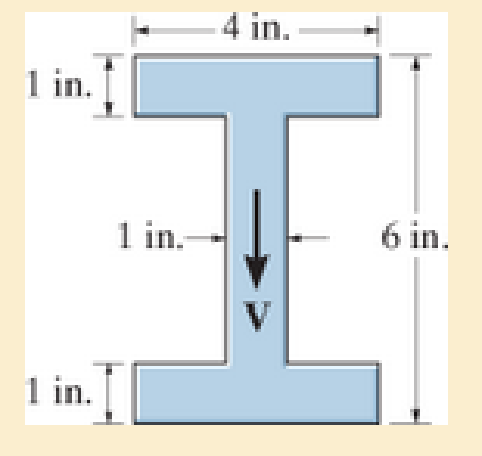
Prob. 7–12
Expert Solution & Answer
Want to see the full answer?
Check out a sample textbook solution
Students have asked these similar questions
The beam is made from a polymer and is subjected to a shear of V = 7 kip. Determine the maximum shear stress in the beam and plot the shear-stress distribution over the cross section. Report the values of the shear stress every0.5 in. of beam depth.
If the wide-flange beam is subjected to a shear force V = 30 kN, determine the maximum shear stress in the beam. Consider w = 200 mm
If the T-beam is subjected to a vertical shear of
V=90kN , determine the maximum shear stress in the
beam. Also, compute the shear-stress jump at the flange-
web junction AB.
100 mm
100 mm
A
100 mm
B
75 mm
150 mm
Chapter 7 Solutions
Mechanics of Materials
Ch. 7.2 - If the beam is subjected to a shear force of V =...Ch. 7.2 - Determine the shear stress at points A and B if...Ch. 7.2 - Determine the absolute maximum shear stress in the...Ch. 7.2 - If the beam is subjected to a shear force of V =20...Ch. 7.2 - If the beam is made from four plates and subjected...Ch. 7.2 - If the wide-flange beam is subjected to a shear of...Ch. 7.2 - If the wide-flange beam is subjected to a shear of...Ch. 7.2 - If the wide-flange beam is subjected to a shear of...Ch. 7.2 - The wood beam has an allowable shear stress of...Ch. 7.2 - The shaft is supported by a thrust bearing at A...
Ch. 7.2 - The shaft is supported by a thrust bearing at A...Ch. 7.2 - Determine the largest shear force V that the...Ch. 7.2 - If the applied shear force V = 18 kip, determine...Ch. 7.2 - The overhang beam is subjected to the uniform...Ch. 7.2 - The beam is made from a polymer and is subjected...Ch. 7.2 - Determine the maximum shear stress in the strut if...Ch. 7.2 - Determine the maximum shear force V that the strut...Ch. 7.2 - If the beam is subjected to a shear of V=15 kN,...Ch. 7.2 - If the wide-flange beam is subjected to a shear of...Ch. 7.2 - If the wide-flange beam is subjected to a shear of...Ch. 7.2 - Determine the length of the cantilevered beam so...Ch. 7.2 - If the beam is made from wood having an allowable...Ch. 7.2 - Determine the shear stress at point B on the web...Ch. 7.2 - Determine the maximum shear stress acting at...Ch. 7.2 - The beam is slit longitudinally along both sides....Ch. 7.2 - The beam is to be cut longitudinally along both...Ch. 7.2 - The beam has a rectangular cross section and is...Ch. 7.2 - The beam in Fig.6-48f is subjected to a fully...Ch. 7.3 - The two identical boards are bolted together to...Ch. 7.3 - Two identical 20-mm-thick plates are bolted to the...Ch. 7.3 - The boards are bolted together to form the...Ch. 7.3 - The boards are bolted together to form the...Ch. 7.3 - The beam is constructed from three boards. If it...Ch. 7.3 - The beam is constructed from three boards....Ch. 7.3 - Prob. 38PCh. 7.3 - A beam is constructed from three boards bolted...Ch. 7.3 - The T-beam is constructed as shown. If each nail...Ch. 7.3 - The member consists of two plastic channel strips...Ch. 7.3 - The beam is made from four boards nailed together...Ch. 7.3 - The beam is made from three polystyrene strips...Ch. 7.5 - A shear force of V=300 kN is applied to the box...Ch. 7.5 - A shear force of V=450 kN is applied to the box...Ch. 7.5 - A shear force of V = 18 kN is applied to the box...Ch. 7.5 - A shear force of V = 18 kN is applied to the box...Ch. 7.5 - The aluminum strut is 10 mm thick and has the...Ch. 7.5 - The aluminum strut is 10 mm thick and has the...Ch. 7.5 - The beam is subjected to a shear force of V=50...Ch. 7.5 - The beam is subjected to a shear force of V=50...Ch. 7.5 - The H-beam is subjected to a shear of V=80 kN...Ch. 7.5 - The H-beam is subjected to a shear of V=80 kN...Ch. 7.5 - The built-up beam is formed by welding together...Ch. 7.5 - The assembly is subjected to a vertical shear of V...Ch. 7 - The beam is fabricated from four boards nailed...Ch. 7 - The T-beam is subjected to a shear of V = 150 kN....Ch. 7 - The member is subject to a shear force of V = 2...Ch. 7 - Determine the shear stress at points B and C on...Ch. 7 - Determine the maximum shear stress acting at...
Knowledge Booster


Learn more about
Need a deep-dive on the concept behind this application? Look no further. Learn more about this topic, mechanical-engineering and related others by exploring similar questions and additional content below.Similar questions
- The beam is subjected to a shear of V=39 kN V=39 kN. Set w=200 mm w=200 mm Part A Determine the web's shear stress at A. Part B Determine the web's shear stress at B.arrow_forwardThe beam is made of Douglas fir having an allowable bending stress of sallow = 1.1 ksi and an allowable shear stress of tallow = 0.70 ksi. Determine the width b if the height h = 2b.arrow_forwardThe H-beam is subjected to a shear of V = 80 kN. Sketch the shear-stress distribution acting along with one of its side segments. Indicate all peak values.arrow_forward
- Determine the absolute maximum bending stress in the beam. Each segment has a rectangular cross section with a base of 4 in. and height of 12 in.arrow_forwardDetermine the internal shear force at a location of x = 2.5 m for the following beam in kN. 3 m 2 KN 5m Xarrow_forwardCalculate the maximum normal and shear stress values for the attached beam at x = 8.5 m. Determine the distribution of the shear stress in the cross-section in the y-axis direction at y=55 mm, y=109.99 mm and y=110.01 from top. The dimensions of the beam are a = 5.5 m, b = 3.0 m and c = 2.5 m, and the cross-sectional dimensions are d = 170 mm and h = 130 mm. The distributed load of the beam has the value q = 3kN / m and the force F = 10kN.arrow_forward
- The composite beam consists of a wood core and two plates of steel. If the allowable bending stress for the wood is (ơallow)w = 20 MPa, and for the steel (ơallow)st = 130 MPa, determine the maximum shear v that can be applied to the beam. Ew = 11 GPa, E = 200 GPa. 125 mm Given: (7allow),vood = 6.5 MPa E n = Ew 200(10°) 11(10°) = 18.182 1 (0.80227)(0.125) = 0.130578(10-³)m* 12 I = 20 mm- 75 mm Failure of wood : 20 mm Mc (om)max = I M(0.0625) 20(10°) M = 41.8 KN•M 0.130578(10 125mm Failure of steel : nMc (ơ1)max = I 18.182(M)(0.0625). 0.130578(10¬³) 130(10“) M = 14.9 kN •m (controls) A maximum moment that can be applied to the beam.arrow_forwardIf the wide-flange beam is subjected to a shear force V = 30 kN, determine the shear force resisted by the web of the beam. Consider w = 200 mmarrow_forwardDetermine the maximum shear stress acting in the fiberglass beam at the section where the internal shears force is maximum. (t1=15 mm, t2=20 mm, h=150 mm, b=50mm)arrow_forward
- The member has a circular cross section. If the allowable bending stress is sallow = 100 MPa, determine the maximum moment M that can be applied to the memberarrow_forwardDetermine the shear stress at points A and B of the web, when the beam is subjected to a shear force V = 15 kN. Consider w = 125 mmarrow_forwardDetermine the maximum bending stress in the beam’s cross section.arrow_forward
arrow_back_ios
SEE MORE QUESTIONS
arrow_forward_ios
Recommended textbooks for you
 Elements Of ElectromagneticsMechanical EngineeringISBN:9780190698614Author:Sadiku, Matthew N. O.Publisher:Oxford University Press
 Mechanics of Materials (10th Edition)Mechanical EngineeringISBN:9780134319650Author:Russell C. HibbelerPublisher:PEARSON
 Thermodynamics: An Engineering ApproachMechanical EngineeringISBN:9781259822674Author:Yunus A. Cengel Dr., Michael A. BolesPublisher:McGraw-Hill Education
 Control Systems EngineeringMechanical EngineeringISBN:9781118170519Author:Norman S. NisePublisher:WILEY
 Mechanics of Materials (MindTap Course List)Mechanical EngineeringISBN:9781337093347Author:Barry J. Goodno, James M. GerePublisher:Cengage Learning
 Engineering Mechanics: StaticsMechanical EngineeringISBN:9781118807330Author:James L. Meriam, L. G. Kraige, J. N. BoltonPublisher:WILEY
Elements Of Electromagnetics
Mechanical Engineering
ISBN:9780190698614
Author:Sadiku, Matthew N. O.
Publisher:Oxford University Press
Mechanics of Materials (10th Edition)
Mechanical Engineering
ISBN:9780134319650
Author:Russell C. Hibbeler
Publisher:PEARSON
Thermodynamics: An Engineering Approach
Mechanical Engineering
ISBN:9781259822674
Author:Yunus A. Cengel Dr., Michael A. Boles
Publisher:McGraw-Hill Education
Control Systems Engineering
Mechanical Engineering
ISBN:9781118170519
Author:Norman S. Nise
Publisher:WILEY
Mechanics of Materials (MindTap Course List)
Mechanical Engineering
ISBN:9781337093347
Author:Barry J. Goodno, James M. Gere
Publisher:Cengage Learning
Engineering Mechanics: Statics
Mechanical Engineering
ISBN:9781118807330
Author:James L. Meriam, L. G. Kraige, J. N. Bolton
Publisher:WILEY
Everything About TRANSVERSE SHEAR in 10 Minutes!! - Mechanics of Materials; Author: Less Boring Lectures;https://www.youtube.com/watch?v=4x0E9yvzfCM;License: Standard Youtube License