
Mechanics of Materials
11th Edition
ISBN: 9780137605514
Author: Russell C. Hibbeler
Publisher: Pearson Education (US)
expand_more
expand_more
format_list_bulleted
Concept explainers
Videos
Textbook Question
Chapter 7.2, Problem 14P
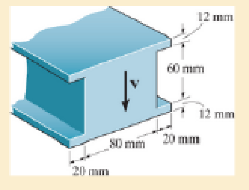
Determine the maximum shear force V that the strut can support if the allowable shear stress for the material is τallow = 40 MPa.
Probs. 7–13/14
Expert Solution & Answer
Want to see the full answer?
Check out a sample textbook solution
Students have asked these similar questions
F12-7. Two identical 20-mm-thick plates are bolted to the
top and bottom flange to form the built-up beam. If the
beam is subjected to a shear force of V = 300 kN, determine
the maximum spacing s of the bolts to the nearest mm if
cach bolt has a shear strength of 30 kN.
-200 mm
20 mm
10 mm
300 mm
ho mm
"20 mm
F7-2
P7-3 Determine the absolute maximum shear stress
developed in the beam.
3kip
61h.
F-3
4. If P = 20KN, determine the shear stress developed in pins at point A and C. The pins
are subjected to double shear as shown, and each has a diameter of 18mm
30° ?
'B
-2 m-
+ 2 m
-2 m
5. The strut is glued to the horizontal member at surface AB. If the strut has thickness
of 25mm and the glue can withstand an average shear stress of 600kPa, determine
the maximum force P that can be applied strut.
50 mm.
60°
B
Chapter 7 Solutions
Mechanics of Materials
Ch. 7.2 - If the beam is subjected to a shear force of V =...Ch. 7.2 - Determine the shear stress at points A and B if...Ch. 7.2 - Determine the absolute maximum shear stress in the...Ch. 7.2 - If the beam is subjected to a shear force of V =20...Ch. 7.2 - If the beam is made from four plates and subjected...Ch. 7.2 - If the wide-flange beam is subjected to a shear of...Ch. 7.2 - If the wide-flange beam is subjected to a shear of...Ch. 7.2 - If the wide-flange beam is subjected to a shear of...Ch. 7.2 - The wood beam has an allowable shear stress of...Ch. 7.2 - The shaft is supported by a thrust bearing at A...
Ch. 7.2 - The shaft is supported by a thrust bearing at A...Ch. 7.2 - Determine the largest shear force V that the...Ch. 7.2 - If the applied shear force V = 18 kip, determine...Ch. 7.2 - The overhang beam is subjected to the uniform...Ch. 7.2 - The beam is made from a polymer and is subjected...Ch. 7.2 - Determine the maximum shear stress in the strut if...Ch. 7.2 - Determine the maximum shear force V that the strut...Ch. 7.2 - If the beam is subjected to a shear of V=15 kN,...Ch. 7.2 - If the wide-flange beam is subjected to a shear of...Ch. 7.2 - If the wide-flange beam is subjected to a shear of...Ch. 7.2 - Determine the length of the cantilevered beam so...Ch. 7.2 - If the beam is made from wood having an allowable...Ch. 7.2 - Determine the shear stress at point B on the web...Ch. 7.2 - Determine the maximum shear stress acting at...Ch. 7.2 - The beam is slit longitudinally along both sides....Ch. 7.2 - The beam is to be cut longitudinally along both...Ch. 7.2 - The beam has a rectangular cross section and is...Ch. 7.2 - The beam in Fig.6-48f is subjected to a fully...Ch. 7.3 - The two identical boards are bolted together to...Ch. 7.3 - Two identical 20-mm-thick plates are bolted to the...Ch. 7.3 - The boards are bolted together to form the...Ch. 7.3 - The boards are bolted together to form the...Ch. 7.3 - The beam is constructed from three boards. If it...Ch. 7.3 - The beam is constructed from three boards....Ch. 7.3 - Prob. 38PCh. 7.3 - A beam is constructed from three boards bolted...Ch. 7.3 - The T-beam is constructed as shown. If each nail...Ch. 7.3 - The member consists of two plastic channel strips...Ch. 7.3 - The beam is made from four boards nailed together...Ch. 7.3 - The beam is made from three polystyrene strips...Ch. 7.5 - A shear force of V=300 kN is applied to the box...Ch. 7.5 - A shear force of V=450 kN is applied to the box...Ch. 7.5 - A shear force of V = 18 kN is applied to the box...Ch. 7.5 - A shear force of V = 18 kN is applied to the box...Ch. 7.5 - The aluminum strut is 10 mm thick and has the...Ch. 7.5 - The aluminum strut is 10 mm thick and has the...Ch. 7.5 - The beam is subjected to a shear force of V=50...Ch. 7.5 - The beam is subjected to a shear force of V=50...Ch. 7.5 - The H-beam is subjected to a shear of V=80 kN...Ch. 7.5 - The H-beam is subjected to a shear of V=80 kN...Ch. 7.5 - The built-up beam is formed by welding together...Ch. 7.5 - The assembly is subjected to a vertical shear of V...Ch. 7 - The beam is fabricated from four boards nailed...Ch. 7 - The T-beam is subjected to a shear of V = 150 kN....Ch. 7 - The member is subject to a shear force of V = 2...Ch. 7 - Determine the shear stress at points B and C on...Ch. 7 - Determine the maximum shear stress acting at...
Knowledge Booster


Learn more about
Need a deep-dive on the concept behind this application? Look no further. Learn more about this topic, mechanical-engineering and related others by exploring similar questions and additional content below.Similar questions
- 7-35. The two members used in the construction of an aircraft fuselage are joined together using a 30° fish-mouth weld. Determine the average normal and average shear stress on the plane of each weld. Assume each inclined plane supports a horizontal force of 2 kN. 375 mm 30 4 kN 4 kN 25 mm 30arrow_forward7-62. Determine the required diameter of the pins at A and B if the allowable shear stress for the material is Tallov - 100 MPa. Both pins are subjected to double shear. 2 KN /m 3.arrow_forwardIf P = 14 kN determine the average shear stress developed in the pins at A, B, and C. All pins are in double shear as shown, and each has a diameter of 15 mm 4P 4P 2P 0.5m 0.5 m 1m 1.5 m 1.5 m 30 Barrow_forward
- The shaft is supported by a thrust bearing at A and a journal bearing at B. If P = 20 kN, determine the absolute maximum shear stress in the shaft.arrow_forwardIf P=5kN, determine the average shear stress in the pins A, B, and C. All pins are in double shear, and each as a diameter of 18 mm. P 0.5 m B 3P -1.5 m- 2 m 6P -1.5 m- P 0.5 marrow_forwardDetermine the maximum shear stress in the strut if it is subjected to a shear force of V = 20 kN.arrow_forward
- *10-4 The link acts as part of the elevator control for a small airplane. If the attached aluminum tube has an inner diameter of 25 mm and a wall thickness of 5 mm, determine the maximum shear stress in the tube when the cable force of 600 N is applied to the cables Also, sketch the shearstress distribution aver the cros section. f00 N 75 mm imm 25 mm 75 m G00Narrow_forward8. If the allowable shear stress for each of the 10-mm-diameter steel pins at A, B, and C is Ellow = 90 MPa, and the allowable normal stress for the 13-mm-diameter rod is Glow = 150 MPa, determine the largest intensity w of the uniform distributed load that can be suspended from the beam. 1.2 m B 0.9 g Probs. 1-87/88arrow_forwardThe board is subjected to a tensile force of 200 lb. Determine the average normal and average shear stress in the wood fibers, which are oriented along plane a–a at 20° with the axis of the board.arrow_forward
- 7-1. The shaft is supported by a smooth thrust bearing at B and a journal bearing at C. Determine the resultant internal loadings acting on the cross section at E. 1800 N 3600 Narrow_forward*7-12. The beam has a rectangular cross section and is made of wood having an allowable shear stress of Tallow = 200 psi. Determine the maximum shear force V that can be developed in the cross section of the beam. Also, plot the shear-stress variation over the cross section. 12 in. 8 in. Prob. 7-12arrow_forwardF7-9. The boards are bolted together to form the built-up beam. If the beam is subjected to a shear force of V = 15 kip, determine the allowable maximum spacing of the bolts to the nearest in. Each bolt has a shear strength of 6 kip. 1 in. 0.5 in. 0.5 in. 4 in. 3 in. 1 in, 1 in. 3 in. 4 in. F7-9arrow_forward
arrow_back_ios
SEE MORE QUESTIONS
arrow_forward_ios
Recommended textbooks for you
 Elements Of ElectromagneticsMechanical EngineeringISBN:9780190698614Author:Sadiku, Matthew N. O.Publisher:Oxford University Press
 Mechanics of Materials (10th Edition)Mechanical EngineeringISBN:9780134319650Author:Russell C. HibbelerPublisher:PEARSON
 Thermodynamics: An Engineering ApproachMechanical EngineeringISBN:9781259822674Author:Yunus A. Cengel Dr., Michael A. BolesPublisher:McGraw-Hill Education
 Control Systems EngineeringMechanical EngineeringISBN:9781118170519Author:Norman S. NisePublisher:WILEY
 Mechanics of Materials (MindTap Course List)Mechanical EngineeringISBN:9781337093347Author:Barry J. Goodno, James M. GerePublisher:Cengage Learning
 Engineering Mechanics: StaticsMechanical EngineeringISBN:9781118807330Author:James L. Meriam, L. G. Kraige, J. N. BoltonPublisher:WILEY
Elements Of Electromagnetics
Mechanical Engineering
ISBN:9780190698614
Author:Sadiku, Matthew N. O.
Publisher:Oxford University Press
Mechanics of Materials (10th Edition)
Mechanical Engineering
ISBN:9780134319650
Author:Russell C. Hibbeler
Publisher:PEARSON
Thermodynamics: An Engineering Approach
Mechanical Engineering
ISBN:9781259822674
Author:Yunus A. Cengel Dr., Michael A. Boles
Publisher:McGraw-Hill Education
Control Systems Engineering
Mechanical Engineering
ISBN:9781118170519
Author:Norman S. Nise
Publisher:WILEY
Mechanics of Materials (MindTap Course List)
Mechanical Engineering
ISBN:9781337093347
Author:Barry J. Goodno, James M. Gere
Publisher:Cengage Learning
Engineering Mechanics: Statics
Mechanical Engineering
ISBN:9781118807330
Author:James L. Meriam, L. G. Kraige, J. N. Bolton
Publisher:WILEY
Understanding Torsion; Author: The Efficient Engineer;https://www.youtube.com/watch?v=1YTKedLQOa0;License: Standard YouTube License, CC-BY