
Mechanics of Materials
11th Edition
ISBN: 9780137605514
Author: Russell C. Hibbeler
Publisher: Pearson Education (US)
expand_more
expand_more
format_list_bulleted
Concept explainers
Videos
Textbook Question
Chapter 7.2, Problem 8P
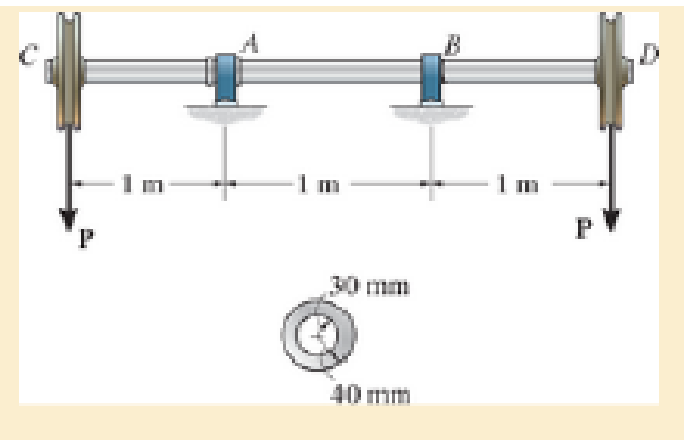
The shaft is supported by a thrust bearing at A and a journal bearing at B. If the shaft is made from a material having an allowable shear stress of τallow=75 MPa, determine the maximum value for P.
Probs. 7–7/8
Expert Solution & Answer
Want to see the full answer?
Check out a sample textbook solution
Students have asked these similar questions
The shaft is supported by a thrust bearing at A and a journal bearing at B. If P = 20 kN, determine the absolute maximum shear stress in the shaft.
Determine the smallest allowable diameter of the shaft which is subjected to the concentrated forces. The journal bearing at A and B only support vertical forces. The allowable bending stress is σallow= 160 MPa
F1= 10kN F2=18kN
L1=500 mm L2= 400mm L3=590mm
The 150-mm-diameter shaft is supported by a
smooth journal bearing at E and a smooth thrust bearing at F.
Determine the maximum shear stress developed in the shaft.
Chapter 7 Solutions
Mechanics of Materials
Ch. 7.2 - If the beam is subjected to a shear force of V =...Ch. 7.2 - Determine the shear stress at points A and B if...Ch. 7.2 - Determine the absolute maximum shear stress in the...Ch. 7.2 - If the beam is subjected to a shear force of V =20...Ch. 7.2 - If the beam is made from four plates and subjected...Ch. 7.2 - If the wide-flange beam is subjected to a shear of...Ch. 7.2 - If the wide-flange beam is subjected to a shear of...Ch. 7.2 - If the wide-flange beam is subjected to a shear of...Ch. 7.2 - The wood beam has an allowable shear stress of...Ch. 7.2 - The shaft is supported by a thrust bearing at A...
Ch. 7.2 - The shaft is supported by a thrust bearing at A...Ch. 7.2 - Determine the largest shear force V that the...Ch. 7.2 - If the applied shear force V = 18 kip, determine...Ch. 7.2 - The overhang beam is subjected to the uniform...Ch. 7.2 - The beam is made from a polymer and is subjected...Ch. 7.2 - Determine the maximum shear stress in the strut if...Ch. 7.2 - Determine the maximum shear force V that the strut...Ch. 7.2 - If the beam is subjected to a shear of V=15 kN,...Ch. 7.2 - If the wide-flange beam is subjected to a shear of...Ch. 7.2 - If the wide-flange beam is subjected to a shear of...Ch. 7.2 - Determine the length of the cantilevered beam so...Ch. 7.2 - If the beam is made from wood having an allowable...Ch. 7.2 - Determine the shear stress at point B on the web...Ch. 7.2 - Determine the maximum shear stress acting at...Ch. 7.2 - The beam is slit longitudinally along both sides....Ch. 7.2 - The beam is to be cut longitudinally along both...Ch. 7.2 - The beam has a rectangular cross section and is...Ch. 7.2 - The beam in Fig.6-48f is subjected to a fully...Ch. 7.3 - The two identical boards are bolted together to...Ch. 7.3 - Two identical 20-mm-thick plates are bolted to the...Ch. 7.3 - The boards are bolted together to form the...Ch. 7.3 - The boards are bolted together to form the...Ch. 7.3 - The beam is constructed from three boards. If it...Ch. 7.3 - The beam is constructed from three boards....Ch. 7.3 - Prob. 38PCh. 7.3 - A beam is constructed from three boards bolted...Ch. 7.3 - The T-beam is constructed as shown. If each nail...Ch. 7.3 - The member consists of two plastic channel strips...Ch. 7.3 - The beam is made from four boards nailed together...Ch. 7.3 - The beam is made from three polystyrene strips...Ch. 7.5 - A shear force of V=300 kN is applied to the box...Ch. 7.5 - A shear force of V=450 kN is applied to the box...Ch. 7.5 - A shear force of V = 18 kN is applied to the box...Ch. 7.5 - A shear force of V = 18 kN is applied to the box...Ch. 7.5 - The aluminum strut is 10 mm thick and has the...Ch. 7.5 - The aluminum strut is 10 mm thick and has the...Ch. 7.5 - The beam is subjected to a shear force of V=50...Ch. 7.5 - The beam is subjected to a shear force of V=50...Ch. 7.5 - The H-beam is subjected to a shear of V=80 kN...Ch. 7.5 - The H-beam is subjected to a shear of V=80 kN...Ch. 7.5 - The built-up beam is formed by welding together...Ch. 7.5 - The assembly is subjected to a vertical shear of V...Ch. 7 - The beam is fabricated from four boards nailed...Ch. 7 - The T-beam is subjected to a shear of V = 150 kN....Ch. 7 - The member is subject to a shear force of V = 2...Ch. 7 - Determine the shear stress at points B and C on...Ch. 7 - Determine the maximum shear stress acting at...
Knowledge Booster


Learn more about
Need a deep-dive on the concept behind this application? Look no further. Learn more about this topic, mechanical-engineering and related others by exploring similar questions and additional content below.Similar questions
- The solid aluminum shaft has a diameter of 50 mm and allowable shear stress of tallow = 60 MPa. Determine the largest torque T1 that can be applied to the shaft if it is also subjected to the other torsional loadings. It is requiredthat T1 act in the direction shown. Also, determine the maximum shear stress within regions CD and DE. 5–7. The solid aluminum shaft has a diameter of 50arrow_forwardThe shaft is made from a solid steel section AB and a tubular portion made of steel and having a brass core. If it is fixed to a rigid support at A, and a torque of T = 50 lb.ft is applied to it at C, determine the rotation angle that occurs at C relative to A and compute the maximum shear stress and maximum shear strain in the brass and steel. Take Gst = 11500 ksi, Gbr = 5600 Ksi. 3 ft 0.5 in. B 1 in. T = 50 lb•ftarrow_forwardThe steel shaft is formed by attaching a hollow shaft to a solid shaft. Determine the shear stress (in Pa) in the hollow shaft using the maximum torque T that can be applied to the ends of the shaft without exceeding a shear stress of 70066350 Pa and angle of twist of 2.5° for the whole shaft. Use 6 = 83000000000 Pafor the shaft, x = 2.25 m, and y = 1.63 m. Round off the final answer to two decimal places. T 100 mm 70 mm 70 mm yarrow_forward
- The plastic hexagonal tube is subjected to a torque of 150 N # m. Determine the mean dimension a of its sides if the allowable shear stress is tallow = 60 MPa. Each side has a thickness of t = 3 mm.arrow_forwardThe solid steel shaft AC has a diameter of 25 mm and is supported by smooth bearings at D and E. It is coupled to a motor at C, which delivers 3 kW of power to the shaft while it is turning at 50 rev>s. If gears A and B remove1 kW and 2 kW, respectively, determine the maximum shear stress in the shaft within regions AB and BC. The shaft is free to turn in its support bearings D and E.arrow_forwardThe steel step shaft has allowable shear stress of tallow = 8 MPa. If the transition between the cross-sections has a radius r = 4 mm, determine the maximum torque T that can be applied.arrow_forward
- The shaft has an outer diameter of 100 mm and an inner diameter of 80 mm. If it is subjected to the three torques, plot the shear stress distribution along a radial line for the cross section within region CD of the shaft. The smooth bearings at A and B do not resist torque. E 10 kN m B 15 kN m 5 kN-marrow_forwardThe shaft is hollow from A to B and solid from B to C. Determine the maximum shear stress in the shaft. The shaft has an outer diameter of 80 mm, and the thickness of the wall of the hollow segment is 10 mm.arrow_forward= 5-6. The solid shaft has a diameter of 0.75 in. If it is subjected to the torques shown, determine the maximum shear stress developed in regions BC and DE of the shaft. The bearings at A and Fallow free rotation of the shaft. B 20 lb-ft 35 lb-ft 40 lb-ft 25 lb-ft Probs. 5-6/7arrow_forward
- The solid 35-mm-diameter shaft is used to transmit the torques applied to the gears. The shaft is made of steel A-36 with E = 200 GPa and G = 75 GPa a. Determine the absolute maximum shear stress on the shaft. b. Determine the angle of twist of the end B with respect to end A. c. The shaft is now change d to a hollowed shaft with an outside diameter of 40 mm. What inner diameter is required to resist the same torque with the same maximum shear stress?arrow_forwardThe two solid steel shafts are connected by gears C and F and 9 in. 2,5 in. supported by smooth bearings at B, D, and E. The upper shaft is fixed at G. If the shear modulus is G = 11 x 10° ksi, determine the angle of rotation of end A when the torque of 700 lb - ft is аpplied. E 1.75 in. -3 in. 4 ft B 700 lb ft 5 ftarrow_forwardThe steel shaft is formed by attaching a hollow shaft to a solid shaft. Determine the shear stress (in Pa) in the hollow shaft using the maximum torque T that can be applied to the ends of the shaft without exceeding a shear stress of 70033753 Pa and angle of twist of 2.49ᴼ for the whole shaft. Use G = 83000000000 Pafor the shaft, x = 2.28 m, and y = 1.87 m. Round off the final answer to two decimal places.arrow_forward
arrow_back_ios
SEE MORE QUESTIONS
arrow_forward_ios
Recommended textbooks for you
 Elements Of ElectromagneticsMechanical EngineeringISBN:9780190698614Author:Sadiku, Matthew N. O.Publisher:Oxford University Press
 Mechanics of Materials (10th Edition)Mechanical EngineeringISBN:9780134319650Author:Russell C. HibbelerPublisher:PEARSON
 Thermodynamics: An Engineering ApproachMechanical EngineeringISBN:9781259822674Author:Yunus A. Cengel Dr., Michael A. BolesPublisher:McGraw-Hill Education
 Control Systems EngineeringMechanical EngineeringISBN:9781118170519Author:Norman S. NisePublisher:WILEY
 Mechanics of Materials (MindTap Course List)Mechanical EngineeringISBN:9781337093347Author:Barry J. Goodno, James M. GerePublisher:Cengage Learning
 Engineering Mechanics: StaticsMechanical EngineeringISBN:9781118807330Author:James L. Meriam, L. G. Kraige, J. N. BoltonPublisher:WILEY
Elements Of Electromagnetics
Mechanical Engineering
ISBN:9780190698614
Author:Sadiku, Matthew N. O.
Publisher:Oxford University Press
Mechanics of Materials (10th Edition)
Mechanical Engineering
ISBN:9780134319650
Author:Russell C. Hibbeler
Publisher:PEARSON
Thermodynamics: An Engineering Approach
Mechanical Engineering
ISBN:9781259822674
Author:Yunus A. Cengel Dr., Michael A. Boles
Publisher:McGraw-Hill Education
Control Systems Engineering
Mechanical Engineering
ISBN:9781118170519
Author:Norman S. Nise
Publisher:WILEY
Mechanics of Materials (MindTap Course List)
Mechanical Engineering
ISBN:9781337093347
Author:Barry J. Goodno, James M. Gere
Publisher:Cengage Learning
Engineering Mechanics: Statics
Mechanical Engineering
ISBN:9781118807330
Author:James L. Meriam, L. G. Kraige, J. N. Bolton
Publisher:WILEY
Everything About COMBINED LOADING in 10 Minutes! Mechanics of Materials; Author: Less Boring Lectures;https://www.youtube.com/watch?v=N-PlI900hSg;License: Standard youtube license