
Loose Leaf for Engineering Circuit Analysis Format: Loose-leaf
9th Edition
ISBN: 9781259989452
Author: Hayt
Publisher: Mcgraw Hill Publishers
expand_more
expand_more
format_list_bulleted
Concept explainers
Videos
Textbook Question
Chapter 8, Problem 10E
The switch in Fig. 8.56 has been closed for a long time, before being opened at t = 0. (a) Find an expression for v(t) and i(t) in the figure for t > 0, and (b) evaluate v and i at t = 1 ms.
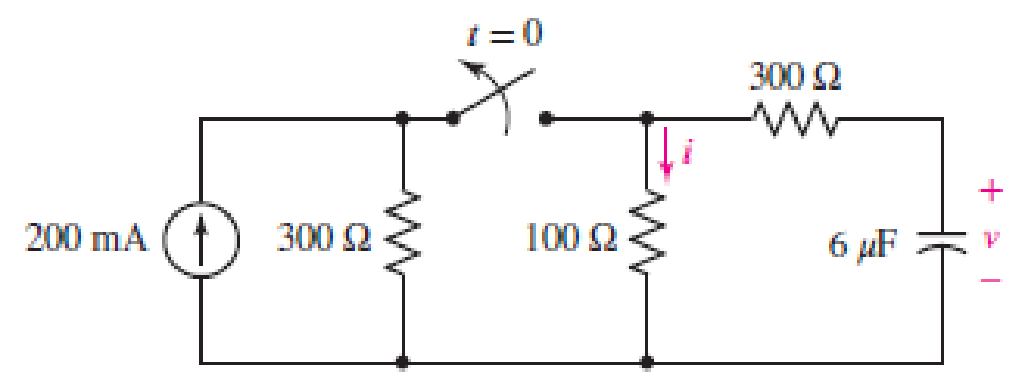
FIGURE 8.56
Expert Solution & Answer
Want to see the full answer?
Check out a sample textbook solution
Students have asked these similar questions
The switch in the circuit of Fig. 8.91, often called a make-before-break switch
(since during switching it briefly makes contact to both parts of the circuit to
ensure a smooth electrical transition), moves to position b at t = 0 only after
being in position a long enough to ensure all initial transients arising from
turning on the sources have long since decayed. (a) Determine the power
dissipated by the 5 -
resistor at t = 0−. (b) Determine the power dissipated in
the 3 -
resistor at t = 2 ms.
For a certain source-free parallel RLC circuit, R = 1 k , C = 3 μF, and L is such that the circuit response is overdamped. (a) Determine the value of L. (b) Write the equation for the voltage v across the resistor if it is known that v(0−) = 9 V and dv/dt|t=0+ = 2 V/s.
The switch in the circuit shown in the figure below has been open for a long time. It closes at t = 0s, then 1-Calculate the initial stored energy in the capacitor 2- Find the current iR(t) for t >= 0. 3- Plot the current iR(t) for t >= 0.
Chapter 8 Solutions
Loose Leaf for Engineering Circuit Analysis Format: Loose-leaf
Ch. 8.1 - For the circuit in Fig. 8.2, what value of...Ch. 8.1 - Noting carefully how the circuit changes once the...Ch. 8.2 - In a source-free series RC circuit, find the...Ch. 8.3 - Prob. 4PCh. 8.3 - Prob. 5PCh. 8.4 - Prob. 6PCh. 8.4 - Prob. 7PCh. 8.4 - Prob. 8PCh. 8.5 - Evaluate each of the following at t = 0.8: (a)...Ch. 8.6 - For the circuit of Fig. 8.37, find vc(t) at t...
Ch. 8.7 - Prob. 11PCh. 8.7 - The voltage source 60 40u(t) V is in series with...Ch. 8.7 - Prob. 13PCh. 8.8 - Prob. 14PCh. 8.8 - Prob. 15PCh. 8 - A source-free RC circuit has R = 4 k and C = 22 F,...Ch. 8 - A source-free RC circuit has v(0) = 12 V and R =...Ch. 8 - The resistor in the circuit of Fig. 8.51 has been...Ch. 8 - Prob. 4ECh. 8 - Prob. 5ECh. 8 - Prob. 6ECh. 8 - Prob. 7ECh. 8 - Prob. 8ECh. 8 - Prob. 9ECh. 8 - The switch in Fig. 8.56 has been closed for a long...Ch. 8 - For the circuit in Fig. 8.56, find (a) the total...Ch. 8 - Design a capacitor-based circuit that can achieve...Ch. 8 - (a) Graph the function f (t) = 10e2t over the...Ch. 8 - The current i(t) flowing through a 1 k resistor is...Ch. 8 - Radiocarbon dating has a similar exponential time...Ch. 8 - For the circuit of Fig. 8.4, compute the time...Ch. 8 - Design a circuit which will produce a current of 1...Ch. 8 - Prob. 18ECh. 8 - Prob. 19ECh. 8 - Referring to the circuit shown in Fig. 8.11,...Ch. 8 - Prob. 21ECh. 8 - With the assumption that the switch in the circuit...Ch. 8 - The switch in Fig. 8.57 has been closed since...Ch. 8 - The switch in the circuit of Fig. 8.58 has been...Ch. 8 - Assuming the switch initially has been open for a...Ch. 8 - (a) Obtain an expression for v(t), the voltage...Ch. 8 - For the circuit of Fig. 8.61, determine ix, iL,...Ch. 8 - Prob. 28ECh. 8 - Prob. 29ECh. 8 - Prob. 30ECh. 8 - Prob. 31ECh. 8 - (a) Obtain an expression for vx as labeled in the...Ch. 8 - Prob. 33ECh. 8 - Prob. 34ECh. 8 - Prob. 35ECh. 8 - Prob. 36ECh. 8 - Prob. 37ECh. 8 - The switch in Fig. 8.70 is moved from A to B at t...Ch. 8 - Prob. 39ECh. 8 - Prob. 40ECh. 8 - Evaluate the following functions at t = 1, 0, and...Ch. 8 - Prob. 42ECh. 8 - Prob. 43ECh. 8 - Prob. 44ECh. 8 - You can use MATLAB to represent the unit-step...Ch. 8 - With reference to the circuit depicted in Fig....Ch. 8 - For the circuit given in Fig. 8.75, (a) determine...Ch. 8 - Prob. 48ECh. 8 - Prob. 49ECh. 8 - You build a portable solar charging circuit...Ch. 8 - The switch in the circuit of Fig. 8.78 has been...Ch. 8 - The switch in the circuit of Fig. 8.78 has been...Ch. 8 - Prob. 53ECh. 8 - Prob. 54ECh. 8 - Prob. 55ECh. 8 - For the circuit represented in Fig. 8.82, (a)...Ch. 8 - Prob. 58ECh. 8 - Prob. 59ECh. 8 - For the circuit given in Fig. 8.85, (a) determine...Ch. 8 - The circuit depicted in Fig. 8.86 contains two...Ch. 8 - Prob. 62ECh. 8 - Prob. 63ECh. 8 - A series RL circuit has a voltage that steps from...Ch. 8 - For the two-source circuit of Fig. 8.89, note that...Ch. 8 - (a) Obtain an expression for iL as labeled in Fig....Ch. 8 - Obtain an expression for i(t) as labeled in the...Ch. 8 - Obtain an expression for i1 as indicated in Fig....Ch. 8 - Plot the current i(t) in Fig. 8.93 if (a) R = 10 ;...Ch. 8 - A dc motor can be modeled as a series RL circuit...Ch. 8 - Prob. 71ECh. 8 - Prob. 72ECh. 8 - A series RC sequentially switched circuit has R =...Ch. 8 - Refer to the circuit of Fig. 8.95, which contains...Ch. 8 - In the circuit of Fig. 8.95, a 3 mF capacitor is...Ch. 8 - Prob. 78E
Knowledge Booster


Learn more about
Need a deep-dive on the concept behind this application? Look no further. Learn more about this topic, electrical-engineering and related others by exploring similar questions and additional content below.Similar questions
- In the circuit , the resistor isadjusted for critical damping. The initial capacitor voltage is 20 V, andthe initial inductor current is 30 mA.1. Find the numerical value of R.2. Find the numerical values of i and di/dt immediately after theswitch is closed.3. Find vC(t) for t≥0.arrow_forwardCalculate the current in an RLC circuit with resistances R=11 ohms, L=0.1 H, and C=10^-2 F that is linked to the source V(t)= 10sin 377t. Assume that the capacitor charge and current are both zero at time t=0.arrow_forwardFor the two-source circuit of Fig. 8.89, note that one source is always on. (a) Obtain an expression for i(t) valid for all t; (b) determine at what time the energy stored in the inductor reaches 99 percent of its maximum value.arrow_forward
- No energy is stored in the 100 mH inductor or the 0.4μF capacitor when theswitch in the circuit shown is closed. Find vC(t) for t≥0arrow_forwardThe resistance, inductance, and capacitance in a parallel RLC circuit in (Figure 1) are 0.4 kΩ, 5 H, and 5 μF, respectively.Calculate the minimum root of the characteristic equation that describes the voltage response of the circuitCalculate the maximum root of the characteristic equation that describes the voltage response of the circuit.arrow_forwardThe following circuit has the following values:R = 40 Ω, L = 2,5 μH and C = 4nF.a)Assuming that the switch has been closed for a long time, determine the capacitor voltage and inductor current values just before opening of the key, that is, at = 0-.b)Calculate the expression for the current i(t), from the moment the switch is opened in t = 0.arrow_forward
- Show the comparison between the 2nd order damped spring model and the 2nd RLC circuit system.arrow_forward1) The circuit shown below is initially, for t < 0, with capacitor C connected to a battery (Vbat = 12 V).The key is switched at t = 0, disconnecting the battery and turning on the capacitor to the rest of the circuit.a)Calculate the circuit current in the time domain, i(t).b) In practice, after how long can the energy stored in the circuit be considered to be irrelevant (close to zero)?arrow_forwarddifferential equations applications. A 12-volt battery is connected to a series circuit in which the inductor is 1/2 henry and the resistance is 10 ohms. Determine current i, if the initial current is zero.arrow_forward
- An RL circuit has an emf given (in volts) by 4 cos t, a resistance of 100 ohms, an inductance of 4 henries, and no initial current. Find the time when the current is 2 A for the first timarrow_forwardConsider the circuit on the left. DC voltage u1(t ≥ 0) = U is applied at time t = 0. Both meshes must include the input voltage. At time t = 0, the capacitors are free of energy. The following applies: τ = R*C. Derive the 2nd order differential equation for the capacitor voltage u2(t).arrow_forwardThe circuit elements in the circuit L=50 mH, and C=0.2 μF. The initial inductor current is−45 mA and the initial capacitor voltage is 15 V.4. The resistance is increased to 312.5 Ω. Find the expression for v(t) for t≥0.arrow_forward
arrow_back_ios
SEE MORE QUESTIONS
arrow_forward_ios
Recommended textbooks for you
 Introductory Circuit Analysis (13th Edition)Electrical EngineeringISBN:9780133923605Author:Robert L. BoylestadPublisher:PEARSON
 Delmar's Standard Textbook Of ElectricityElectrical EngineeringISBN:9781337900348Author:Stephen L. HermanPublisher:Cengage Learning
 Programmable Logic ControllersElectrical EngineeringISBN:9780073373843Author:Frank D. PetruzellaPublisher:McGraw-Hill Education
 Fundamentals of Electric CircuitsElectrical EngineeringISBN:9780078028229Author:Charles K Alexander, Matthew SadikuPublisher:McGraw-Hill Education
 Electric Circuits. (11th Edition)Electrical EngineeringISBN:9780134746968Author:James W. Nilsson, Susan RiedelPublisher:PEARSON
 Engineering ElectromagneticsElectrical EngineeringISBN:9780078028151Author:Hayt, William H. (william Hart), Jr, BUCK, John A.Publisher:Mcgraw-hill Education,
Introductory Circuit Analysis (13th Edition)
Electrical Engineering
ISBN:9780133923605
Author:Robert L. Boylestad
Publisher:PEARSON
Delmar's Standard Textbook Of Electricity
Electrical Engineering
ISBN:9781337900348
Author:Stephen L. Herman
Publisher:Cengage Learning
Programmable Logic Controllers
Electrical Engineering
ISBN:9780073373843
Author:Frank D. Petruzella
Publisher:McGraw-Hill Education
Fundamentals of Electric Circuits
Electrical Engineering
ISBN:9780078028229
Author:Charles K Alexander, Matthew Sadiku
Publisher:McGraw-Hill Education
Electric Circuits. (11th Edition)
Electrical Engineering
ISBN:9780134746968
Author:James W. Nilsson, Susan Riedel
Publisher:PEARSON
Engineering Electromagnetics
Electrical Engineering
ISBN:9780078028151
Author:Hayt, William H. (william Hart), Jr, BUCK, John A.
Publisher:Mcgraw-hill Education,
ENA 9.2(1)(En)(Alex) Sinusoids & Phasors - Explanation with Example 9.1 ,9.2 & PP 9.2; Author: Electrical Engineering Academy;https://www.youtube.com/watch?v=vX_LLNl-ZpU;License: Standard YouTube License, CC-BY
Electrical Engineering: Ch 10 Alternating Voltages & Phasors (8 of 82) What is a Phasor?; Author: Michel van Biezen;https://www.youtube.com/watch?v=2I1tF3ixNg0;License: Standard Youtube License