
Loose Leaf for Engineering Circuit Analysis Format: Loose-leaf
9th Edition
ISBN: 9781259989452
Author: Hayt
Publisher: Mcgraw Hill Publishers
expand_more
expand_more
format_list_bulleted
Concept explainers
Videos
Textbook Question
Chapter 8, Problem 25E
Assuming the switch initially has been open for a really, really long time, (a) obtain an expression for iW in the circuit of Fig. 8.59, which is valid for all t ≥ 0; (b) calculate iW at t = 0 and t = 1.3 ns.
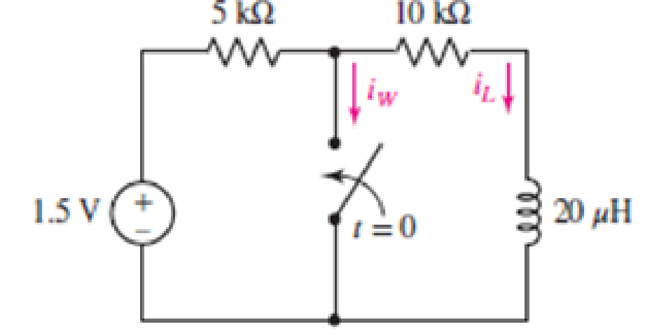
Figure 8.59
Expert Solution & Answer
Want to see the full answer?
Check out a sample textbook solution
Students have asked these similar questions
Calculate initial conditions for inductor current and capacitor voltage in circuit presented in Fig.
8.3. Assume: L=1H, C=0.5F, R=1Ω, e(t) = 10 2 sin(t + 45 ) V, i(t) = 2sin(t − 45 ) A.
The circuit elements in the circuit L=50 mH, and C=0.2 μF. The initial inductor current is−45 mA and the initial capacitor voltage is 15 V.4. The resistance is increased to 312.5 Ω. Find the expression for v(t) for t≥0.
identify the following
1. If the pole’s real value is positive and is located on the right side of the S-plane. The system exponentially ____________.2. Is a continuous connection of branches from one node to another with all arrowheads in the same direction.3. Knowing the location of the pole in the S-plane determines the ______________ of the system.
Chapter 8 Solutions
Loose Leaf for Engineering Circuit Analysis Format: Loose-leaf
Ch. 8.1 - For the circuit in Fig. 8.2, what value of...Ch. 8.1 - Noting carefully how the circuit changes once the...Ch. 8.2 - In a source-free series RC circuit, find the...Ch. 8.3 - Prob. 4PCh. 8.3 - Prob. 5PCh. 8.4 - Prob. 6PCh. 8.4 - Prob. 7PCh. 8.4 - Prob. 8PCh. 8.5 - Evaluate each of the following at t = 0.8: (a)...Ch. 8.6 - For the circuit of Fig. 8.37, find vc(t) at t...
Ch. 8.7 - Prob. 11PCh. 8.7 - The voltage source 60 40u(t) V is in series with...Ch. 8.7 - Prob. 13PCh. 8.8 - Prob. 14PCh. 8.8 - Prob. 15PCh. 8 - A source-free RC circuit has R = 4 k and C = 22 F,...Ch. 8 - A source-free RC circuit has v(0) = 12 V and R =...Ch. 8 - The resistor in the circuit of Fig. 8.51 has been...Ch. 8 - Prob. 4ECh. 8 - Prob. 5ECh. 8 - Prob. 6ECh. 8 - Prob. 7ECh. 8 - Prob. 8ECh. 8 - Prob. 9ECh. 8 - The switch in Fig. 8.56 has been closed for a long...Ch. 8 - For the circuit in Fig. 8.56, find (a) the total...Ch. 8 - Design a capacitor-based circuit that can achieve...Ch. 8 - (a) Graph the function f (t) = 10e2t over the...Ch. 8 - The current i(t) flowing through a 1 k resistor is...Ch. 8 - Radiocarbon dating has a similar exponential time...Ch. 8 - For the circuit of Fig. 8.4, compute the time...Ch. 8 - Design a circuit which will produce a current of 1...Ch. 8 - Prob. 18ECh. 8 - Prob. 19ECh. 8 - Referring to the circuit shown in Fig. 8.11,...Ch. 8 - Prob. 21ECh. 8 - With the assumption that the switch in the circuit...Ch. 8 - The switch in Fig. 8.57 has been closed since...Ch. 8 - The switch in the circuit of Fig. 8.58 has been...Ch. 8 - Assuming the switch initially has been open for a...Ch. 8 - (a) Obtain an expression for v(t), the voltage...Ch. 8 - For the circuit of Fig. 8.61, determine ix, iL,...Ch. 8 - Prob. 28ECh. 8 - Prob. 29ECh. 8 - Prob. 30ECh. 8 - Prob. 31ECh. 8 - (a) Obtain an expression for vx as labeled in the...Ch. 8 - Prob. 33ECh. 8 - Prob. 34ECh. 8 - Prob. 35ECh. 8 - Prob. 36ECh. 8 - Prob. 37ECh. 8 - The switch in Fig. 8.70 is moved from A to B at t...Ch. 8 - Prob. 39ECh. 8 - Prob. 40ECh. 8 - Evaluate the following functions at t = 1, 0, and...Ch. 8 - Prob. 42ECh. 8 - Prob. 43ECh. 8 - Prob. 44ECh. 8 - You can use MATLAB to represent the unit-step...Ch. 8 - With reference to the circuit depicted in Fig....Ch. 8 - For the circuit given in Fig. 8.75, (a) determine...Ch. 8 - Prob. 48ECh. 8 - Prob. 49ECh. 8 - You build a portable solar charging circuit...Ch. 8 - The switch in the circuit of Fig. 8.78 has been...Ch. 8 - The switch in the circuit of Fig. 8.78 has been...Ch. 8 - Prob. 53ECh. 8 - Prob. 54ECh. 8 - Prob. 55ECh. 8 - For the circuit represented in Fig. 8.82, (a)...Ch. 8 - Prob. 58ECh. 8 - Prob. 59ECh. 8 - For the circuit given in Fig. 8.85, (a) determine...Ch. 8 - The circuit depicted in Fig. 8.86 contains two...Ch. 8 - Prob. 62ECh. 8 - Prob. 63ECh. 8 - A series RL circuit has a voltage that steps from...Ch. 8 - For the two-source circuit of Fig. 8.89, note that...Ch. 8 - (a) Obtain an expression for iL as labeled in Fig....Ch. 8 - Obtain an expression for i(t) as labeled in the...Ch. 8 - Obtain an expression for i1 as indicated in Fig....Ch. 8 - Plot the current i(t) in Fig. 8.93 if (a) R = 10 ;...Ch. 8 - A dc motor can be modeled as a series RL circuit...Ch. 8 - Prob. 71ECh. 8 - Prob. 72ECh. 8 - A series RC sequentially switched circuit has R =...Ch. 8 - Refer to the circuit of Fig. 8.95, which contains...Ch. 8 - In the circuit of Fig. 8.95, a 3 mF capacitor is...Ch. 8 - Prob. 78E
Knowledge Booster


Learn more about
Need a deep-dive on the concept behind this application? Look no further. Learn more about this topic, electrical-engineering and related others by exploring similar questions and additional content below.Similar questions
- The switch in the circuit of Fig. 8.91, often called a make-before-break switch (since during switching it briefly makes contact to both parts of the circuit to ensure a smooth electrical transition), moves to position b at t = 0 only after being in position a long enough to ensure all initial transients arising from turning on the sources have long since decayed. (a) Determine the power dissipated by the 5 - resistor at t = 0−. (b) Determine the power dissipated in the 3 - resistor at t = 2 ms.arrow_forwardFor the two-source circuit of Fig. 8.89, note that one source is always on. (a) Obtain an expression for i(t) valid for all t; (b) determine at what time the energy stored in the inductor reaches 99 percent of its maximum value.arrow_forwardCalculate the current in an RLC circuit with resistances R=11 ohms, L=0.1 H, and C=10^-2 F that is linked to the source V(t)= 10sin 377t. Assume that the capacitor charge and current are both zero at time t=0.arrow_forward
- If the roots of the characteristic equation are -3,0 then the system is _________________________. Marginally stable Conditionally stable Stable Unstablearrow_forwardFor the circuit below with the switch closed and then opening at t=0, and R1= 3Ω, R2= 7Ω, C = 0.2H, ig = 8A, vs = 2v, calculate the initial condition. Develop the differential equation for the solution for t > 0. Calculate the current ia(t) for all times.arrow_forwarddifferential equations applications. A 12-volt battery is connected to a series circuit in which the inductor is 1/2 henry and the resistance is 10 ohms. Determine current i, if the initial current is zero.arrow_forward
- The switch in the circuit shown in the figure below has been open for a long time. It closes at t = 0s, then 1-Calculate the initial stored energy in the capacitor 2- Find the current iR(t) for t >= 0. 3- Plot the current iR(t) for t >= 0.arrow_forward*Assume that at the instant the 2 A dc current source is applied to the circuit in (Figure 1), the initial current in the 25 mH inductor is 1 A, and the initial voltage on the capacitor is 50 V (positive at the upper terminal).* Pt A. Find the expression for iL(t) for t≥0 if R equals 12.5 Ωarrow_forwardThe switch in Fig. 8.73 is moved from A to B at t = 0 after being at A for along time. This places the two capacitors in series, thus allowing equal andopposite dc voltages to be trapped on the capacitors. (a) Determine v1(0−),v2(0−), and vR(0−). (b) Find v1(0+), v2(0+), and vR(0+). (c) Determine thetime constant of vR(t). (d) Find vR(t), t > 0. (e) Find i(t). ( f ) Find v1(t) andv2(t) from i(t) and the initial values. (g) Show that the stored energy at t = ∞plus the total energy dissipated in the 20 k-resistor is equal to the energystored in the capacitors at t = 0.arrow_forward
- Consider the RLC circuit shown where the initial current flowing through the circuit at time t = 0 is I_0 = 5 and the initial charge on the capacitor at time t = 0 is Q_0 = 2. The components have values of R = 100 ohms, L = 5 H, and C = 1/450,500 F. Write the differential equation for Q(t), the charge across the capacitor, assuming the voltage source V(t) = 0arrow_forward2. 7.22 The switch in the circuit has been in the left positionfor a long time. At t=0 it moves to the right position and stays there. 1. a) Write the expression for the capacitor voltage, v(t), for t≥0arrow_forwardA resistor (R = 1 Ω), inductor (L = 0.1 H) and capacitor (C = 0.1 F) are connected in series, and the current I(t) through the circuit is measured as shown in the image below Assuming that the capacitor is uncharged at t = 0, and that the circuit is electrically small (such that propagation times between components can be neglected), find (or approximate where necessary) for times t = [0 : 0.1 : 0.4] (i.e. do not calculate at t = 0.5) : (shown in the image below)arrow_forward
arrow_back_ios
SEE MORE QUESTIONS
arrow_forward_ios
Recommended textbooks for you
 Introductory Circuit Analysis (13th Edition)Electrical EngineeringISBN:9780133923605Author:Robert L. BoylestadPublisher:PEARSON
 Delmar's Standard Textbook Of ElectricityElectrical EngineeringISBN:9781337900348Author:Stephen L. HermanPublisher:Cengage Learning
 Programmable Logic ControllersElectrical EngineeringISBN:9780073373843Author:Frank D. PetruzellaPublisher:McGraw-Hill Education
 Fundamentals of Electric CircuitsElectrical EngineeringISBN:9780078028229Author:Charles K Alexander, Matthew SadikuPublisher:McGraw-Hill Education
 Electric Circuits. (11th Edition)Electrical EngineeringISBN:9780134746968Author:James W. Nilsson, Susan RiedelPublisher:PEARSON
 Engineering ElectromagneticsElectrical EngineeringISBN:9780078028151Author:Hayt, William H. (william Hart), Jr, BUCK, John A.Publisher:Mcgraw-hill Education,
Introductory Circuit Analysis (13th Edition)
Electrical Engineering
ISBN:9780133923605
Author:Robert L. Boylestad
Publisher:PEARSON
Delmar's Standard Textbook Of Electricity
Electrical Engineering
ISBN:9781337900348
Author:Stephen L. Herman
Publisher:Cengage Learning
Programmable Logic Controllers
Electrical Engineering
ISBN:9780073373843
Author:Frank D. Petruzella
Publisher:McGraw-Hill Education
Fundamentals of Electric Circuits
Electrical Engineering
ISBN:9780078028229
Author:Charles K Alexander, Matthew Sadiku
Publisher:McGraw-Hill Education
Electric Circuits. (11th Edition)
Electrical Engineering
ISBN:9780134746968
Author:James W. Nilsson, Susan Riedel
Publisher:PEARSON
Engineering Electromagnetics
Electrical Engineering
ISBN:9780078028151
Author:Hayt, William H. (william Hart), Jr, BUCK, John A.
Publisher:Mcgraw-hill Education,
ENA 9.2(1)(En)(Alex) Sinusoids & Phasors - Explanation with Example 9.1 ,9.2 & PP 9.2; Author: Electrical Engineering Academy;https://www.youtube.com/watch?v=vX_LLNl-ZpU;License: Standard YouTube License, CC-BY
Electrical Engineering: Ch 10 Alternating Voltages & Phasors (8 of 82) What is a Phasor?; Author: Michel van Biezen;https://www.youtube.com/watch?v=2I1tF3ixNg0;License: Standard Youtube License