
Concept explainers
Videos
8–55 to
8–58 For the pressure cylinder defined in the problem specified in the table, the gas pressure is cycled between pg and pg/2. Determine the fatigue factor of safety for the bolts using the Goodman criterion.
| Problem Number | Originating Problem Number |
| 8–55 | 8–33 |
| 8–56 | 8–34 |
| 8–57 | 8–35 |
| 8–58 | 8–36 |
8–33 to
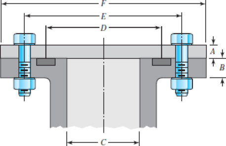
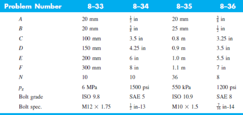
8–36 The figure illustrates the non-permanent connection of a steel cylinder head to a grade 30 castiron pressure vessel using N bolts. A confined gasket seal has an effective sealing diameter D. The cylinder stores gas at a maximum pressure pg. For the specifications given in the table for the specific problem assigned, select a suitable bolt length from the preferred sizes in Table A–17, then determine the yielding factor of safety np, the load factor nL, and the joint separation factor n0.
11Russell, Burdsall & Ward, Inc., Metal Forming Specialists, Mentor, Ohio.
Problems 8–33 to 8–36
Want to see the full answer?
Check out a sample textbook solution
Chapter 8 Solutions
Connect 1-semester Access Card For Shigley's Mechanical Engineering Design


- The layout of transmission shaft carrying two pulleys B and C and supported on bearings A and D is shown in Figure below. Power is supplied to the shaft by means of a vertical belt on pulley B, that is then transmitted to pulley C carrying a horizontal belt. The maximum tension in belt on pulley B is 2.5 kN. The angle of wrap for both the pulleys is 180o and the coefficient of friction 0.24. The shaft is made of plain carbon steel 30C8 (Syt=400 N/mm2) and the factor of safety is 3. Determine the shaft diameter on strength basis.arrow_forwardDetermine the safe tensile load for fine series bolts of (a) M 24and (b) M 38. Assume that the bolts are not initially stressed and take the safe tensile stress as 450MPa.arrow_forwardThe figure gives the cross-section of a grade 25 cast-iron pressure vessel. A total of N bolts are to be used to resist a separating force of 150 kN. (a) Determine kb, km, and C. (b) Find the number of bolts required for a load factor of 2 where the bolts may be reused when the joint is taken apart. (c) With the number of bolts obtained in part (b), determine the realized load factor for overload, the yielding factor of safety, and the load factor for joint separation. Use (SI) units as it appliesarrow_forward
- Figure 8-19 is a cross-section of ASTM A36. A total of N bolts are to be used to resist a separating force of 7258.97N is one bolt. A) Determine kb,km, and C B) Determine the realized load factor for overload, the yielding factor of safety, and the load factor of joint separation.arrow_forwardThe figure shows a shaft mounted in bearings at A and D and having pulleys at B and C. The forces shown acting on the pulley surfaces represent the belt tensions. The shaft is to be made of AISI 1035 CD steel. The shaft is rotating at speed of 1000 rpm. Find the minimum factor of safety for fatigue based on infinite life. If the life is not infinite, estimate the number of cycles. Be sure to check for yielding. Take shaft diameter to be 1.5 inches.arrow_forwardQ) A helical compression spring of a mechanism is subjected to Pas =120 N 19ad cycle. The diameter if the wire is 3 mm, with a spring index of € = 7 P, =4N and .The spring is made of oil-hardened and tempered steel, with”« ~ L0t dm Determine the factor of safety in fatigue loading.arrow_forward
- A motor is to transmit 150 kW to a piece of mechanical equipment. The power is transmitted through a solid structural steel shaft. Failure is by yielding, and the factor of safety is 1.25. The designer has the freedom to operate the motor at 60 rpm or 6000 rpm. For each case, determine the minimum shaft diameter. Shafts are available with diameters in increments of 5 mm. If weight is important, which speed would be used?arrow_forwardA cylinder with a nominal 2.5 in ID, a 4.0 in OD, and a 3.0 in length is to be mated with a solid shaft with a nominal 2.5 in diameter. A medium drive fit is desired (as defined in Table 7-9). The cylinder and shaft are made from steel, with Sy = 100 kpsi and E = 30 Mpsi. The coefficient of friction for the steel interface is 0.7. a. Specify the maximum and minimum allowable diameters for both the cylinder hole and the shaft. b. Determine the torque that can be transmitted through this joint, assuming the shaft and cylinder are both manufactured within their tolerances such that the minimum interference is achieved. c. Suppose the shaft and cylinder are both manufactured within their tolerances such that the maximum interference is achieved. Check for yielding of the cylinder at its inner radius by finding the following: i. The pressure at the interface ii. The tangential and radial stresses in the cylinder, at its inner radius. iii. The factor of safety for static yielding of the…arrow_forward5. Design a sleeve coupling for the transmission of 12 kW at 300 rpm by two connected steel shafts. Take service factor KS 1.25. The sleeve is made of CI. The key and the shaft are made of the same material. Allowable stress: Shear stresses in key and shaft 50 MPa Crushing stress in key= 100 MPa Shear stress in CI sleeve = 10 MPaarrow_forward
- In the figure below the clamping force on the pipe is (331.7 lb), knowing that a single threaded screw Acme with major diameter (1 in) is used with coefficient of friction (0.2135). If booth screw and nut are made from 1030 - hot rolled Carbon Steel. Determine: 1- The tightening and loosening torques. 2- Thread screw and nut shear safety factors in case of double threads are in engagement. 3.3 in 2 7.2 in 32 3 in hingearrow_forwardA rotating shaft of 40×4 mm AISI 1018 cold-drawn steel tubing has a 6 mm diameter hole drilled transversely through it. Estimate the factor of safety guarding against fatigue and static failures using the Gerber and Langer failure criteria for the following loading conditions: a. The shaft is subjected to a completely reversed torque of 120 N.m in phase with a completely reversed bending moment of 150 N.m. b. The shaft is subjected to a pulsating torque fluctuating from 20 to 160 N.m and as steady bending moment of 150 N.m.arrow_forwardThe horsepower required to drive 40 mm power screw having a pitch of 8 mm, is 3 hp. The screw is single threaded and is made of cold-rolled steel with Sut=550 MPa and Sy=380 MPa and the nut is made of ASTM NO.20 cast iron. The nut height is 50 mm. A factor of safety for possible failures in the threads is 3. If the screw is rotating at a speed of 50 rpm, determine; a) the maximum force that can be applied by the nut b) the efficiency of screw-nut c) the coefficient of friction between the nut and the screw.arrow_forward
 Elements Of ElectromagneticsMechanical EngineeringISBN:9780190698614Author:Sadiku, Matthew N. O.Publisher:Oxford University Press
 Mechanics of Materials (10th Edition)Mechanical EngineeringISBN:9780134319650Author:Russell C. HibbelerPublisher:PEARSON
 Thermodynamics: An Engineering ApproachMechanical EngineeringISBN:9781259822674Author:Yunus A. Cengel Dr., Michael A. BolesPublisher:McGraw-Hill Education
 Control Systems EngineeringMechanical EngineeringISBN:9781118170519Author:Norman S. NisePublisher:WILEY
 Mechanics of Materials (MindTap Course List)Mechanical EngineeringISBN:9781337093347Author:Barry J. Goodno, James M. GerePublisher:Cengage Learning
 Engineering Mechanics: StaticsMechanical EngineeringISBN:9781118807330Author:James L. Meriam, L. G. Kraige, J. N. BoltonPublisher:WILEY