
Videos
The yielding factor of safety.
The load factor.
The joint separation factor.
Answer to Problem 40P
The yielding factor of safety is
The load factor is
The joint separation factor is
Explanation of Solution
Write the expression tensile load per bolt.
Here, tensile load per bolt is
Write the expression for cross section area of sealing.
Here, area is
Write the expression for grip.
Here, total thickness of plate and washer is
Write the expression for length of bolt.
Write the expression for threaded length.
Here threaded length is
Write the expression for area of unthreaded portion.
Here, the area of unthreaded portion is
Write the expression for length of unthreaded portion in grip.
Here, the length of unthreaded portion in grip is
Write the expression for length of threaded portion in grip
Here, length of threaded portion in grip is
Write the expression for bolt stiffness.
Here, bolt stiffness is
Write the expression for stiffness of top frusta.
Here, the stiffness of top frusta is
Write the expression for total spring rate of the member.
Here, the total spring rate of the member is
Write the expression for joint stiffness constant.
Here, joint stiffness constant is
Write the expression for preload.
Here, preload is
Write the expression for load factor
Here, load factor is
Write the expression for yielding factor of safety.
Here, yielding factor of safety is
Write the expression for load factor guarding against joint separation.
Here, load factor guarding against joint is
Write the expression for total external load.
Here, the total load is
Write the expression for load on the bolt.
Here, the load on the bolt is
Write the expression for cross section area of the cylinder.
Here, area of cylinder is
Conclusion:
Substitute
Substitute
Substitute
Substitute
Substitute
Substitute
Substitute
Substitute
Refer to table 8-1 “Diameter and areas of unified screw threads UNC and UNF”, obtain tensile stress area for nominal diameter of
Refer to table 8-9 “SAE specification for steel”, to obtain the minimum proof strength as
Substitute
Figure (1) shows the frustum of the cone for compressive load on the joint.
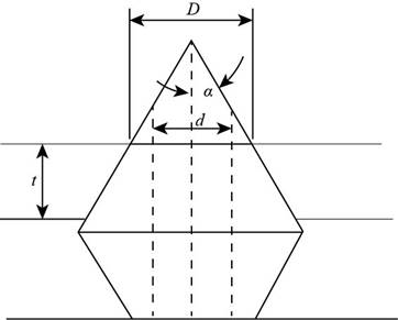
Figure-(1)
Write the expression for thickness of frusta.
Write the expression for diameter of the top frusta.
Substitute
Write the expression for thickness of middle frusta.
Write the expression for diameter of the middle frusta.
Substitute
Write the expression for thickness of lower frusta.
Write the expression for diameter of the lower frusta.
Substitute
Substitute
Substitute
Substitute
Substitute
Substitute
Substitute
Substitute
Thus the load factor is
Substitute
Thus the yielding factor of safety is
Substitute
Thus the load factor against joint separation is
Want to see more full solutions like this?
Chapter 8 Solutions
Connect 1-semester Access Card For Shigley's Mechanical Engineering Design


- A mild steel shaft has to transmit 75 kW at 200 rpm. Design a cast Iron flange coupling for the shaft. The allowable stresses are Shear stress for the shaft and keys 40 N/mm²Shear stress for bolts = 28 N/mm²Shear stress for C.I. coupling = 20 N/mm² Take wearing stress as twice the shear stress value and number of bolts for coupling as 6.arrow_forward3. Design a compression coupling for a shaft to transmit 1300 N-m. The allowable shear stress for the shaft and key is 40 MPa and the number of bolts connecting the two halves are 4. The permissible tensile stress for the bolts material is 70 MPa. The coefficient of friction between the muff and the shaft surface may be taken as 0.3.arrow_forwardThe layout of transmission shaft carrying two pulleys B and C and supported on bearings A and D is shown in Figure below. Power is supplied to the shaft by means of a vertical belt on pulley B, that is then transmitted to pulley C carrying a horizontal belt. The maximum tension in belt on pulley B is 2.5 kN. The angle of wrap for both the pulleys is 180o and the coefficient of friction 0.24. The shaft is made of plain carbon steel 30C8 (Syt=400 N/mm2) and the factor of safety is 3. Determine the shaft diameter on strength basis.arrow_forward
- Determine the safe tensile load for fine series bolts of (a) M 24and (b) M 38. Assume that the bolts are not initially stressed and take the safe tensile stress as 450MPa.arrow_forwardA rigid coupling with 30 inches of bolt circle diameter transmits a torque of 18,000 lb-in. The coupling material has a yield strength of 90,000 psi. The coupling is fastened by six bolts. Assume design factor of N=3 Calculate the diameter of each bolt.arrow_forwardA right angled bell crank lever is to be designed to raise a load of 5 kN at the short arm end. The lengths of short and long arms are 100 and 450 mm respectively. The lever and the pins are made of steel 30C8 (S = 400 N/mm2). And the factor of safety is 5.the permissible bearing pressure on the pin is 10 N/mm². The lever has a rectangular cross section and the ratio of width to thickness is 3:1. The length to diameter ratio of the fulcrum pin is 1.25:1. Calculate (i) The diameter and length of the fulcrum pin (ii) The dimensions of the cross section.arrow_forward
- 8. Design a clamp coupling for transmitting 25 kW at 300 rpm. Allowable shear stresses in shaft and key are 50 MPa and 45 MPa, respectively. The number of bolts joining the two halves of muff is 4. The permissible tensile stress in the bolt is 70 MPa and the permissible crushing stress in the key is 90 MPa. The coeffi cient of friction between the muff of the CI and the shaft of steel is 0.20.arrow_forwardA cap screw, ¾ in.-10-UNC-2, with a hexagonal head that is 9/16 in. thick, carries a tensile load of 3000 lb. If the material is AISI 1015, cold drawn, find the factor of safety based on ultimate strengths of a. the threaded shank, b. the head against being sheared off, and c. the bearing surface under the head. d. Is there any need to consider the strength of standard cap-screw heads in design?arrow_forwardA cap screw, ¾ in.-10-UNC-2, with a hexagonal head that is 9/16 in. thick, carries a tensile load of 3000 lb. If the material is AISI 1015, cold drawn, find the factor of safety based on ultimate strengths of a.the threaded shank, b.the head against being sheared off, and c.the bearing surface under the head. d.Is there any need to consider the strength of standard cap-screw heads in design?arrow_forward
- (7) The cylinder head of a 10”x18” refrigerant compressor is attached by 10 stud bolts made of SAE grade 5. The maximum cylinder pressure is 350psi. (a) What size of bolt is to be used? (b) What approximate tightening torque should be applied to induce a tightening stress of 0.9 time of the proof stress?arrow_forwardDesign a typical rigid flange coupling for connecting a motor and a centrifugal pump shafts. The coupling needs to transmit 15 KW at 1000 rpm. The allowable shear stresses of the shaft, key and bolt materials are 60 MPa, 50 MPa and 25 MPa respectively. The shear modulus of the shaft material may be taken as 84GPa. The angle of twist of the shaft should be limited to 1 degree in 20 times the shaft diameter. Note: show complete solutionarrow_forwardUsing safety factor of (3) , determine a minimum diameter for the shaft shown in FIGURE 2. The shaft material AISI 1050 HR ( hot rolled ) steel . The power to be transmitted is (8 KW) at ( 900 rpm). The diameter of the pulley is (250 mm ) and the ratio of belt tensions is (2.5 ). (90 percent ) reliability is desired.arrow_forward
 Elements Of ElectromagneticsMechanical EngineeringISBN:9780190698614Author:Sadiku, Matthew N. O.Publisher:Oxford University Press
 Mechanics of Materials (10th Edition)Mechanical EngineeringISBN:9780134319650Author:Russell C. HibbelerPublisher:PEARSON
 Thermodynamics: An Engineering ApproachMechanical EngineeringISBN:9781259822674Author:Yunus A. Cengel Dr., Michael A. BolesPublisher:McGraw-Hill Education
 Control Systems EngineeringMechanical EngineeringISBN:9781118170519Author:Norman S. NisePublisher:WILEY
 Mechanics of Materials (MindTap Course List)Mechanical EngineeringISBN:9781337093347Author:Barry J. Goodno, James M. GerePublisher:Cengage Learning
 Engineering Mechanics: StaticsMechanical EngineeringISBN:9781118807330Author:James L. Meriam, L. G. Kraige, J. N. BoltonPublisher:WILEY