
Connect 1-semester Access Card For Shigley's Mechanical Engineering Design
10th Edition
ISBN: 9780077591632
Author: Richard G Budynas; Keith J Nisbett
Publisher: McGraw-Hill Education
expand_more
expand_more
format_list_bulleted
Concept explainers
Videos
Textbook Question
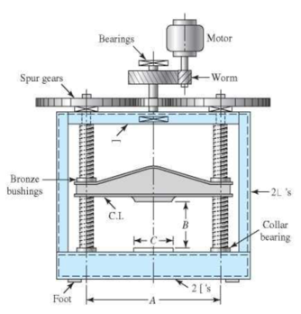
Chapter 8, Problem 5P
The machine shown in the figure can be used for a tension test but not for a compression test. Why? Can both screws have the same hand?
Expert Solution & Answer
Want to see the full answer?
Check out a sample textbook solution
Students have asked these similar questions
The roughly position of the automobile jack shown in the figure is a square screw with a single blade at both ends. ABC is controlled by a bolt (right-hand threaded in A, left-handed in C). square of the bolt screw has a pitch of 2.5 mm and an average diameter of 9 mm. between the bolt and the jack limbs The coefficient of static friction is 0.15, taking into account the position and load shown, you can use the jack Find the magnitude of the torque that must be applied to raise it.
An oval profile straightening machine is shown in the adjacent figure. The movement bolt in the mechanism is single-ended, 80mm diameter and 10mm. It has a square screw with a step. Tightening the movement bolt to the profile An axial force of 10 kN is required as a force. The average diameter between the handle and the bolt is 60 mm. with bolt The friction coefficient between the nut and bolt and the handle is 0.12. The length of the force arm is given as 500 mm. i) Applying the bolt to the lever to apply the desired axial load Find the required force. ii) Find the efficiency of the mechanism. iii) Checking the bolt's security taking into account the A-A cross-section Please pay. Yield strength of bolt Syield strenght= 420 MPa
The figure below is a schematic drawing of a shaft that supports two V-belt pulleys. The loose belt tension on the pulley at A is 15% of the tension on the tight side. The shaft material has a yield strength of 300 MPa and an ultimate tensile strength of 520 MPa. Calculate the shaft diameter.
Chapter 8 Solutions
Connect 1-semester Access Card For Shigley's Mechanical Engineering Design
Ch. 8 - A power screw is 25 mm in diameter and has a...Ch. 8 - Using the information in the footnote of Table...Ch. 8 - Show that for zero collar friction the efficiency...Ch. 8 - A single-threaded power screw is 25 mm in diameter...Ch. 8 - The machine shown in the figure can be used for a...Ch. 8 - The press shown for Prob. 8-5 has a rated load of...Ch. 8 - For the screw clamp shown, a force is applied at...Ch. 8 - The C clamp shown in the figure for Prob. 8-7 uses...Ch. 8 - Find the power required to drive a 1.5-in power...Ch. 8 - A single square-thread power screw has an input...
Ch. 8 - Prob. 11PCh. 8 - An M14 2 hex-head bolt with a nut is used to...Ch. 8 - Prob. 13PCh. 8 - A 2-in steel plate and a 1-in cast-iron plate are...Ch. 8 - Repeat Prob. 8-14 with the addition of one 12 N...Ch. 8 - A 2-in steel plate and a 1-in cast-iron plate are...Ch. 8 - Two identical aluminum plates are each 2 in thick,...Ch. 8 - Prob. 18PCh. 8 - A 30-mm thick AISI 1020 steel plate is sandwiched...Ch. 8 - Prob. 20PCh. 8 - Prob. 21PCh. 8 - Prob. 22PCh. 8 - A 2-in steel plate and a 1-in cast-iron plate are...Ch. 8 - An aluminum bracket with a 12-in thick flange is...Ch. 8 - An M14 2 hex-head bolt with a nut is used to...Ch. 8 - A 34 in-16 UNF series SAE grade 5 bolt has a 34-in...Ch. 8 - From your experience with Prob. 8-26, generalize...Ch. 8 - Prob. 28PCh. 8 - Prob. 29PCh. 8 - Prob. 30PCh. 8 - For a bolted assembly with eight bolts, the...Ch. 8 - Prob. 32PCh. 8 - 8-33 to 8-36 The figure illustrates the...Ch. 8 - 8-33 to 8-36 The figure illustrates the...Ch. 8 - 8-33 to 8-36 The figure illustrates the...Ch. 8 - 8-33 to 8-36 The figure illustrates the...Ch. 8 - Prob. 37PCh. 8 - Prob. 38PCh. 8 - 837 to 840 Repeat the requirements for the problem...Ch. 8 - Prob. 40PCh. 8 - 841 to 844 For the pressure vessel defined in the...Ch. 8 - Prob. 42PCh. 8 - Prob. 43PCh. 8 - Prob. 44PCh. 8 - Bolts distributed about a bolt circle are often...Ch. 8 - The figure shows a cast-iron bearing block that is...Ch. 8 - Prob. 47PCh. 8 - Prob. 48PCh. 8 - Prob. 49PCh. 8 - Prob. 50PCh. 8 - 851 to 854 For the pressure cylinder defined in...Ch. 8 - Prob. 52PCh. 8 - 851 to 854 For the pressure cylinder defined in...Ch. 8 - 851 to 854 For the pressure cylinder defined in...Ch. 8 - 855 to 858 For the pressure cylinder defined in...Ch. 8 - 855 to 858 For the pressure cylinder defined in...Ch. 8 - 855 to 858 For the pressure cylinder defined in...Ch. 8 - For the pressure cylinder defined in the problem...Ch. 8 - A 1-in-diameter hot-rolled AISI 1144 steel rod is...Ch. 8 - The section of the sealed joint shown in the...Ch. 8 - Prob. 61PCh. 8 - Prob. 62PCh. 8 - Prob. 63PCh. 8 - Prob. 64PCh. 8 - Using the Goodman fatigue criterion, repeat Prob....Ch. 8 - The figure shows a bolted lap joint that uses SAE...Ch. 8 - Prob. 67PCh. 8 - A bolted lap joint using ISO class 5.8 bolts and...Ch. 8 - Prob. 69PCh. 8 - The figure shows a connection that employs three...Ch. 8 - A beam is made up by bolting together two cold...Ch. 8 - Prob. 72PCh. 8 - Prob. 73PCh. 8 - Prob. 74PCh. 8 - A vertical channel 152 76 (see Table A7) has a...Ch. 8 - The cantilever bracket is bolted to a column with...Ch. 8 - Prob. 77PCh. 8 - The figure shows a welded fitting which has been...Ch. 8 - Prob. 79PCh. 8 - Prob. 80PCh. 8 - Prob. 81P
Knowledge Booster


Learn more about
Need a deep-dive on the concept behind this application? Look no further. Learn more about this topic, mechanical-engineering and related others by exploring similar questions and additional content below.Similar questions
- A small lab scale has a rigid L-shaped frame ABC consisting of a horizontal arm AB (length b = 10 in.) and a vertical arm BC (length c = 7 in.) pivoted al point B. The pivot is attached to the outer frame BCD that stands on a laboratory bench. The position of the pointer al C is controlled by a spring, Jt = 5 lb/in., that is attached to a threaded rod. The pitch of the threads is p = 1/16 in. Under application of load W, 12 revolutions of the nut are required to bring the pointer back to the mark. Calculate the weight W.arrow_forwardAn inflatable structure used by a traveling circus has the shape of a half-circular cylinder with closed ends (see figure). The fabric and plastic structure is inflated by a small blower and has a radius of 40 ft when fully inflated. A longitudinal scam runs the entire length of the "ridge" of the structure. If the longitudinal scam along the ridge tears open when it is subjected to a tensile load of 540 pounds per inch of seam, what is the factor of safety n against tearing when the internal pressure is 0,5 psi and the structure is fully inflated?arrow_forwardDraw the free body diagrams for each part in the figures below:arrow_forward
- The following figure shows a belt brake system operating on a brake drum of the hoisting mechanism. It consists of a cylinder with a diameter of 325 mm, the end of which is the elastic belt connected to both ends of the elastic belt by a crank arm articulated at B and the angle of rotation = 225 degrees. And the coefficient of friction is 0.3 and the latching force is f. Find the necessary F to generate a torque of 350 on the cylinder while it is rotating in the direction shown? Note that s = c = 135mm a = 500mm. 35mmarrow_forwardInformation about the clamp assembly in the figure is given below. Thread diameter 12 mm, root diameter 10.16 mm, pitch 1.5 mm, screw profile angle 2α=60, friction surface of table A diameter 10 mm, friction between plate A-screw end surface coefficient 0.15 and screw-nut friction coefficient 0.15 is given. If a hand force of 200N is applied to the vise arm, if applied, a) How much force is applied to the clamped part. b) Calculate the efficiency of the vise.arrow_forwardThe uniform bar AB in the figure weighs 40 kgf and is free to rotate about the hinge at B. The man weighs 80 kgf and pulls on the rope that supports the bar. The rope passes through a fixed semi-cylinder with friction coefficient 0.4. Calculate the minimum vertical force that the man must exert to maintain his balance.arrow_forward
- The block brake, as shown in the figure, provides a braking torque of 376 N-m. The diameter of the brake drum is 258 mm. The coefficient of friction is 0.3. Find: a. The force (P), in Newtons, to be applied at the end of the lever for the clockwise rotation of the brake drum b. The force (P), in Newtons, to be applied at the end of the lever for the counter clockwise rotation of the brake drum; and c. The location of the pivot or fulcrum, in mm, to make the brake self-locking for the clockwise rotation of the brake drum.arrow_forwardA single-piece bicycle crank is shown below under the following load: the rider pedals forward with a vertical force Fp = 500 N on the left pedal and no force on the right pedal. The chain exerts a force Fc on the chainring. The spindle is a solid cylinder with a diameter d = 16 mm. 1. Draw a free-body diagram of the entire crankset and find the reactions at the ball bearings and the force from the chain.arrow_forwardA single block brake is shown in the figure. The diameter of the drum is 250 mm and the angle of contact is 103.7°. If the operating force of 661N is applied at the end of a lever and the coefficient of friction between the drum and the lining is 0.35, determine: a. The tangential braking force, Ft, in Newtons b. The braking the torque transmitted by the block brake in N-m.arrow_forward
- A differential band brake is shown in the figure. The diameter of the drum is 800 mm. The coefficient of friction between the band and the drum is 0.3 and the angle of embrace is 240°. When a force of 777 N is applied at the free end of the lever, find: a. The maximum force, in Newtons, in the band for the clockwise rotation of the drum b. The minimum force, in Newtons, in the band for the clockwise rotation of the drum c. The maximum force, in Newtons, in the band for the counter clockwise rotation of the drum d. The minimum force, in Newtons, in the band for the counter clockwise rotation of the drum e. The torque which can be applied by the brake, in N-m, for the clockwise rotation of the drum.arrow_forwardRefer to the figure, which force member from the options is equal to 5.66k compression?arrow_forward(3) A single-threaded jackscrew has square threads. The screw diameter is l in. and there are 4 threads/in. A friction collar has a 2-in. outside diameter and an l-in. inside diameter. The coefficient of friction is 0.1 for the collar and 0.15 for the threads. How much force must be applied on a l2-in. (radius) jack lever to raise a load of 1,000lb?arrow_forward
arrow_back_ios
SEE MORE QUESTIONS
arrow_forward_ios
Recommended textbooks for you
 Mechanics of Materials (MindTap Course List)Mechanical EngineeringISBN:9781337093347Author:Barry J. Goodno, James M. GerePublisher:Cengage Learning
Mechanics of Materials (MindTap Course List)
Mechanical Engineering
ISBN:9781337093347
Author:Barry J. Goodno, James M. Gere
Publisher:Cengage Learning
EVERYTHING on Axial Loading Normal Stress in 10 MINUTES - Mechanics of Materials; Author: Less Boring Lectures;https://www.youtube.com/watch?v=jQ-fNqZWrNg;License: Standard YouTube License, CC-BY