
Connect 1-semester Access Card For Shigley's Mechanical Engineering Design
10th Edition
ISBN: 9780077591632
Author: Richard G Budynas; Keith J Nisbett
Publisher: McGraw-Hill Education
expand_more
expand_more
format_list_bulleted
Videos
Textbook Question
Chapter 8, Problem 70P
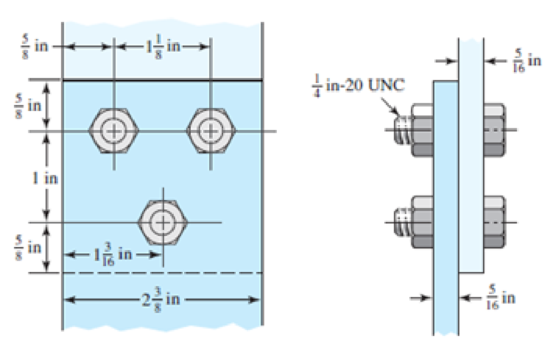
The figure shows a connection that employs three SAE grade 4 bolts. The tensile shear load on the joint is 5000 lbf. The members are cold-drawn bars of AISI 1020 steel. Assume the bolt threads do not extend into the joint. Find the factor of safety for each possible mode of failure.
Problem 8–70
Expert Solution & Answer
Want to see the full answer?
Check out a sample textbook solution
Students have asked these similar questions
The figure gives the cross-section of a grade 25 cast-iron pressure vessel. A total of N bolts are to be used to resist a separating force of 150 kN.
(a) Determine kb, km, and C.
(b) Find the number of bolts required for a load factor of 2 where the bolts may be reused when the joint is taken apart.
(c) With the number of bolts obtained in part (b), determine the realized load factor for overload, the yielding factor of safety, and the load factor for joint separation.
Use (SI) units as it applies
Determine the safe tensile load for fine series bolts of (a) M 24and (b) M 38. Assume that the bolts are not initially stressed and take the safe tensile stress as 450MPa.
Figure 8-19 is a cross-section of ASTM A36. A total of N bolts are to be used to resist a separating force of 7258.97N is one bolt.
A) Determine kb,km, and C
B) Determine the realized load factor for overload, the yielding factor of safety, and the load factor of joint separation.
Chapter 8 Solutions
Connect 1-semester Access Card For Shigley's Mechanical Engineering Design
Ch. 8 - A power screw is 25 mm in diameter and has a...Ch. 8 - Using the information in the footnote of Table...Ch. 8 - Show that for zero collar friction the efficiency...Ch. 8 - A single-threaded power screw is 25 mm in diameter...Ch. 8 - The machine shown in the figure can be used for a...Ch. 8 - The press shown for Prob. 8-5 has a rated load of...Ch. 8 - For the screw clamp shown, a force is applied at...Ch. 8 - The C clamp shown in the figure for Prob. 8-7 uses...Ch. 8 - Find the power required to drive a 1.5-in power...Ch. 8 - A single square-thread power screw has an input...
Ch. 8 - Prob. 11PCh. 8 - An M14 2 hex-head bolt with a nut is used to...Ch. 8 - Prob. 13PCh. 8 - A 2-in steel plate and a 1-in cast-iron plate are...Ch. 8 - Repeat Prob. 8-14 with the addition of one 12 N...Ch. 8 - A 2-in steel plate and a 1-in cast-iron plate are...Ch. 8 - Two identical aluminum plates are each 2 in thick,...Ch. 8 - Prob. 18PCh. 8 - A 30-mm thick AISI 1020 steel plate is sandwiched...Ch. 8 - Prob. 20PCh. 8 - Prob. 21PCh. 8 - Prob. 22PCh. 8 - A 2-in steel plate and a 1-in cast-iron plate are...Ch. 8 - An aluminum bracket with a 12-in thick flange is...Ch. 8 - An M14 2 hex-head bolt with a nut is used to...Ch. 8 - A 34 in-16 UNF series SAE grade 5 bolt has a 34-in...Ch. 8 - From your experience with Prob. 8-26, generalize...Ch. 8 - Prob. 28PCh. 8 - Prob. 29PCh. 8 - Prob. 30PCh. 8 - For a bolted assembly with eight bolts, the...Ch. 8 - Prob. 32PCh. 8 - 8-33 to 8-36 The figure illustrates the...Ch. 8 - 8-33 to 8-36 The figure illustrates the...Ch. 8 - 8-33 to 8-36 The figure illustrates the...Ch. 8 - 8-33 to 8-36 The figure illustrates the...Ch. 8 - Prob. 37PCh. 8 - Prob. 38PCh. 8 - 837 to 840 Repeat the requirements for the problem...Ch. 8 - Prob. 40PCh. 8 - 841 to 844 For the pressure vessel defined in the...Ch. 8 - Prob. 42PCh. 8 - Prob. 43PCh. 8 - Prob. 44PCh. 8 - Bolts distributed about a bolt circle are often...Ch. 8 - The figure shows a cast-iron bearing block that is...Ch. 8 - Prob. 47PCh. 8 - Prob. 48PCh. 8 - Prob. 49PCh. 8 - Prob. 50PCh. 8 - 851 to 854 For the pressure cylinder defined in...Ch. 8 - Prob. 52PCh. 8 - 851 to 854 For the pressure cylinder defined in...Ch. 8 - 851 to 854 For the pressure cylinder defined in...Ch. 8 - 855 to 858 For the pressure cylinder defined in...Ch. 8 - 855 to 858 For the pressure cylinder defined in...Ch. 8 - 855 to 858 For the pressure cylinder defined in...Ch. 8 - For the pressure cylinder defined in the problem...Ch. 8 - A 1-in-diameter hot-rolled AISI 1144 steel rod is...Ch. 8 - The section of the sealed joint shown in the...Ch. 8 - Prob. 61PCh. 8 - Prob. 62PCh. 8 - Prob. 63PCh. 8 - Prob. 64PCh. 8 - Using the Goodman fatigue criterion, repeat Prob....Ch. 8 - The figure shows a bolted lap joint that uses SAE...Ch. 8 - Prob. 67PCh. 8 - A bolted lap joint using ISO class 5.8 bolts and...Ch. 8 - Prob. 69PCh. 8 - The figure shows a connection that employs three...Ch. 8 - A beam is made up by bolting together two cold...Ch. 8 - Prob. 72PCh. 8 - Prob. 73PCh. 8 - Prob. 74PCh. 8 - A vertical channel 152 76 (see Table A7) has a...Ch. 8 - The cantilever bracket is bolted to a column with...Ch. 8 - Prob. 77PCh. 8 - The figure shows a welded fitting which has been...Ch. 8 - Prob. 79PCh. 8 - Prob. 80PCh. 8 - Prob. 81P
Knowledge Booster


Learn more about
Need a deep-dive on the concept behind this application? Look no further. Learn more about this topic, mechanical-engineering and related others by exploring similar questions and additional content below.Similar questions
- 3. Design a compression coupling for a shaft to transmit 1300 N-m. The allowable shear stress for the shaft and key is 40 MPa and the number of bolts connecting the two halves are 4. The permissible tensile stress for the bolts material is 70 MPa. The coefficient of friction between the muff and the shaft surface may be taken as 0.3.arrow_forwardA rigid coupling with 30 inches of bolt circle diameter transmits a torque of 18,000 lb-in. The coupling material has a yield strength of 90,000 psi. The coupling is fastened by six bolts. Assume design factor of N=3 Calculate the diameter of each bolt.arrow_forwardA semi-elliptic spring used for automobile suspension, consists of two extra full-length leaves and eight graduated-length leaves, including the master leaf. The centre-to centre distance between the two eyes is 1 m. The leaves are made of steel 55Si2Mo90 (Syt = 1500 N/mm2and E = 207000 N/mm2) and the factor of safety is 2. The maximum spring load is 30 kN. The leaves are pre- stressed so as to equalize stresses in all leaves under maximum load. Determine the dimensions of the cross-section of the leaves and the deflection at the end of the spring.arrow_forward
- A mild steel shaft has to transmit 75 kW at 200 rpm. Design a cast Iron flange coupling for the shaft. The allowable stresses are Shear stress for the shaft and keys 40 N/mm²Shear stress for bolts = 28 N/mm²Shear stress for C.I. coupling = 20 N/mm² Take wearing stress as twice the shear stress value and number of bolts for coupling as 6.arrow_forwardA right angled bell crank lever is to be designed to raise a load of 5 kN at the short arm end. The lengths of short and long arms are 100 and 450 mm respectively. The lever and the pins are made of steel 30C8 (S = 400 N/mm2). And the factor of safety is 5.the permissible bearing pressure on the pin is 10 N/mm². The lever has a rectangular cross section and the ratio of width to thickness is 3:1. The length to diameter ratio of the fulcrum pin is 1.25:1. Calculate (i) The diameter and length of the fulcrum pin (ii) The dimensions of the cross section.arrow_forwardA M20 × C4 bolt of mild steel is having yield stress of 320 MPa and factor of safety 3. The safe static tensile load in kN will bearrow_forward
- How many bolts are required for LRFD and ASD for the bearing-type connection shown, if PD = 50 k and PL = 100 k? A325 3/4 in bolts, threads excluded from shear plane.arrow_forwardIn the figure, the footbridge connection piece is connected to the steel column with the help of 3 bolts. It is desired that the 27 kN load be supported by the bolted connection with a safety factor of 2.3. Calculate the smallest bolt diameter accordingly. (Sut Bolt = 600 MPa)arrow_forwardIn the figure below the clamping force on the pipe is (331.7 lb), knowing that a single threaded screw Acme with major diameter (1 in) is used with coefficient of friction (0.2135). If booth screw and nut are made from 1030 - hot rolled Carbon Steel. Determine: 1- The tightening and loosening torques. 2- Thread screw and nut shear safety factors in case of double threads are in engagement. 3.3 in 2 7.2 in 32 3 in hingearrow_forward
- An M30 × 3.5 ISO grade 8.8 bolt is used in a joint at a preload levelrecommended for reused connections, and the joint is subject to a repeated tensilefatigue load of P = 65 kN per bolt. The joint constant is C = 0.25.a) Determine the static load factors; b) The factor of safety guarding against a fatigue failure based on the Goodmanfatigue criterionarrow_forwardDesign a cast iron type flange coupling to transmit 15 kW at 900 rpm from an electric motor to a compressor. Take shear stress for shaft, bolt and key material as 40 MPa.arrow_forward8. Design a clamp coupling for transmitting 25 kW at 300 rpm. Allowable shear stresses in shaft and key are 50 MPa and 45 MPa, respectively. The number of bolts joining the two halves of muff is 4. The permissible tensile stress in the bolt is 70 MPa and the permissible crushing stress in the key is 90 MPa. The coeffi cient of friction between the muff of the CI and the shaft of steel is 0.20.arrow_forward
arrow_back_ios
SEE MORE QUESTIONS
arrow_forward_ios
Recommended textbooks for you
 Elements Of ElectromagneticsMechanical EngineeringISBN:9780190698614Author:Sadiku, Matthew N. O.Publisher:Oxford University Press
 Mechanics of Materials (10th Edition)Mechanical EngineeringISBN:9780134319650Author:Russell C. HibbelerPublisher:PEARSON
 Thermodynamics: An Engineering ApproachMechanical EngineeringISBN:9781259822674Author:Yunus A. Cengel Dr., Michael A. BolesPublisher:McGraw-Hill Education
 Control Systems EngineeringMechanical EngineeringISBN:9781118170519Author:Norman S. NisePublisher:WILEY
 Mechanics of Materials (MindTap Course List)Mechanical EngineeringISBN:9781337093347Author:Barry J. Goodno, James M. GerePublisher:Cengage Learning
 Engineering Mechanics: StaticsMechanical EngineeringISBN:9781118807330Author:James L. Meriam, L. G. Kraige, J. N. BoltonPublisher:WILEY
Elements Of Electromagnetics
Mechanical Engineering
ISBN:9780190698614
Author:Sadiku, Matthew N. O.
Publisher:Oxford University Press
Mechanics of Materials (10th Edition)
Mechanical Engineering
ISBN:9780134319650
Author:Russell C. Hibbeler
Publisher:PEARSON
Thermodynamics: An Engineering Approach
Mechanical Engineering
ISBN:9781259822674
Author:Yunus A. Cengel Dr., Michael A. Boles
Publisher:McGraw-Hill Education
Control Systems Engineering
Mechanical Engineering
ISBN:9781118170519
Author:Norman S. Nise
Publisher:WILEY
Mechanics of Materials (MindTap Course List)
Mechanical Engineering
ISBN:9781337093347
Author:Barry J. Goodno, James M. Gere
Publisher:Cengage Learning
Engineering Mechanics: Statics
Mechanical Engineering
ISBN:9781118807330
Author:James L. Meriam, L. G. Kraige, J. N. Bolton
Publisher:WILEY
Mechanical SPRING DESIGN Strategy and Restrictions in Under 15 Minutes!; Author: Less Boring Lectures;https://www.youtube.com/watch?v=dsWQrzfQt3s;License: Standard Youtube License