Loose Leaf for Engineering Circuit Analysis Format: Loose-leaf
9th Edition
ISBN: 9781259989452
Author: Hayt
Publisher: Mcgraw Hill Publishers
bartleby

Concept explainers

bartleby

Videos

Textbook Question
Book Icon
Chapter 8, Problem 77E

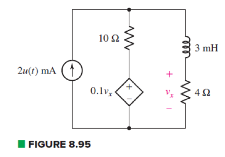
In the circuit of Fig. 8.95, a 3 mF capacitor is accidentally installed instead of the inductor. Unfortunately, that’s not the end of the problems, as it’s later determined that the real capacitor is not really well modeled by an ideal capacitor, and the dielectric has a resistance of 10 kΩ (which should be viewed as connected in parallel to the ideal capacitor). (a) Compute the circuit time constant with and without taking the dielectric resistance into account. By how much does the dielectric change your answer? (b) Calculate vx at t = 200 ms. Does the dielectric resistance affect your answer significantly? Explain.

Chapter 8, Problem 77E, In the circuit of Fig. 8.95, a 3 mF capacitor is accidentally installed instead of the inductor.

(a)

Expert Solution
Check Mark
To determine

Find the value of circuit time constant with and without taking dielectric resistance and explain the change in time constant by dielectric resistance.

Answer to Problem 77E

Value of time constant without dielectric is 40.8ms value of time constant with dielectric is 40.7446ms and value of percentage change in time constant is 0.136%.

Explanation of Solution

Given Data:

Value of capacitor by which the 3 mH inductor is replaced is 3mF and

Value of dielectric resistance is 10.

Formula used:

The expression for resistance is as follows:

R=vi (1)

Here,

v is the voltage ,

i is the current and

R is value of resistance.

The expression for the circuit time constant is as follows:

τ=ReqC (2)

Here,

τ is the circuit time constant,

Req is the equivalent resistance across the capacitor and

C is the value of capacitance.

Calculation:

To find equivalent resistance of a circuit seen by the capacitor, open circuit the inductor and replace all independent sources by their internal resistances. That is, replace current source by open circuit.

Circuit contains dependent voltage source. So to find equivalent resistance connect an arbitrary voltage source of 1V across open circuit terminal.

The circuit diagram is redrawn as shown in Figure 1.

Loose Leaf for Engineering Circuit Analysis Format: Loose-leaf, Chapter 8, Problem 77E , additional homework tip  1

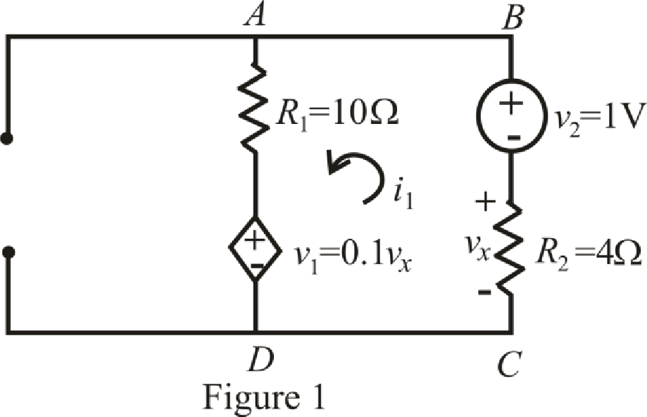
Refer to the redrawn Figure 1.

Circuit is drawn for without dielectric resistor.

The expression for Kirchhoff’s voltage law in mesh DABCD is as follows:

v1i1R1+v2+vx=0 (3)

Here,

v1 and v2 are the voltage in loop DABCD,

vx is voltage across resistor R2,

i1 is the current flowing in loop DABCD and

R1 is the resistances in the circuit.

Substitute 0.1vx for v1, 10Ω for R1 and 1V for v2 in equation (3):

0.1vxi1(10Ω)+1V+vx=0

0.9vx10i1+1V=0 (4)

The expression for vx is as follows:

vx=i1R2 (5)

Here,

vx is voltage across resistor R2,

i1 is the current flowing in loop DABCD and

R2 is the resistances in the circuit.

Substitute 4Ω for R2 in equation (5):

vx=i1(4Ω)

Substitute i1(4Ω) for vx in equation (4):

0.9(i1(4Ω))10i1+1V=03.6i110i1+1V=0

13.6i1+1V=0 (6)

Rearrange equation (6) for i1:

13.6i1=1V

Simplify for i1:

i1=0.07353A

Substitute 1V for v and 0.07353A for i in equation (1):

R=1V0.07353A=13.6Ω

Substitute 13.6Ω for Req and 3 mF for C in equation (2):

τ=(13.6Ω)(3 mF)=40.8ms

So, value of time constant without dielectric is 40.8ms.

To find equivalent resistance of a circuit, independent sources are replaced by their internal resistances. Therefore, replace current source by open circuit.

Circuit is containing dependent voltage source. So, to find equivalent resistance connect a voltage source of 1V across open circuit terminal.

The circuit diagram is redrawn as shown in Figure 2.

Loose Leaf for Engineering Circuit Analysis Format: Loose-leaf, Chapter 8, Problem 77E , additional homework tip  2

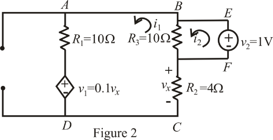
Refer to the redrawn Figure 2:

Circuit is drawn for resistor with dielectric.

The expression for KVL in mesh DABCD is as follows:

v1i1R1+(i2i1)R3+vx=0 (7)

Here,

v1 is the voltage in loop DABCD,

vx is voltage across resistor R2,

i1 is the current flowing in loop DABCD,

i2 is the current flowing in loop FEBCF and

R1 is the resistances in the circuit.

The expression for KVL in mesh FEBCF is as follows:

v2+(i2i1)R3=0 (8)

Here,

v2 is the voltage in loop FEBCF,

i1 is the current flowing in loop DABCD,

i2 is the current flowing in loop FEBCF and

R3 is the resistances in the circuit.

Substitute 0.1vx for v1, 10 for R3 and 10Ω for R1 in equation (7):

0.1vxi1(10Ω)+(i2i1)10+vx=00.9vx10i1+(i2i1)10000Ω=0             {1=1000Ω}

0.9vx10010i1+i210000Ω=0 (9)

Substitute i1(4Ω) for vx in equation (9):

0.9(i1(4Ω))10010i1+i210000Ω=03.6i110010i1+i210000Ω=0

10013.6i1+i210000Ω=0 (10)

Rearrange (10) for i2:

i2=1.00136i1 (11)

Substitute 1V for v2 and 10 for R3 in equation (8):

1V+(i2i1)10=01V+(i2i1)10000Ω=0                            {1=1000Ω}

1V+10000i210000i1=0 (12)

Rearrange equation (12) for i1:

i1=1V+10000i210000

Substitute 1V+10000i210000 for i1 in equation (11):

i2=1.00136(1V+10000i210000)

i2=1.00136+10013.6i210000 (13)

Rearrange equation (13) for i2:

13.6i2=1.00136

Simplify for i2:

i2=0.07363A

Substitute 1V for v and 0.07363A for i in equation (1):

R=1V0.07363A=13.5815Ω

Substitute 13.5815Ω for Req and 3 mF for C in equation (2):

τ=(13.5815Ω)(3 mF)=40.7446ms

So value of time constant with dielectric is 40.7446ms.

The expression for percentage change in time constant with dielectric resistor is as follows;

Δτ=τ1τ2τ1×100 (14)

Here,

Δτ is the percentage change in time constant,

τ1 is the value of time constant without dielectric and

τ2 is the value of time constant with dielectric.

Substitute 40.8ms for τ1 and 40.7446ms for τ2 in equation (14):

Δτ=40.8ms40.7446ms40.8s×100=0.0554ms40.8ms×100=0.136%

Conclusion:

Thus, value of time constant without dielectric is 40.8ms value of time constant with dielectric is 40.7446ms and value of percentage change in time constant is 0.136%.

(b)

Expert Solution
Check Mark
To determine

Calculate vx at t=200ms and calculate change in voltage vx by dielectric resistance.

Answer to Problem 77E

Value of voltage vx without dielectric is 0.04372mV, value of voltage vx with dielectric is 0.04938mV and value of percentage change in voltage vx is 11.46%.

Explanation of Solution

Given Data:

Value of time t is 200ms.

Formula used:

The expression for voltage is as follows:

v=iR (15)

Here,

v is the voltage,

i is the current and

R is value of resistance.

The expression for the final response is as follows:

vC(t)=vC()+(vC(0+)vC())etτ (16)

Here,

vC(t) is the voltage across the capacitor,

vC() is the voltage across the capacitor at t=,

vC(0+) is the voltage across the capacitor at t=0+ and

t is the given time

The expression for current flowing through capacitor is as follows:

iC=CdvCdt (17)

Here,

iC is the capacitor current,

C is the capacitor and

vC is the voltage across capacitor.

Calculation:

The circuit diagram is redrawn as shown in Figure 3 for t<0.

Loose Leaf for Engineering Circuit Analysis Format: Loose-leaf, Chapter 8, Problem 77E , additional homework tip  3

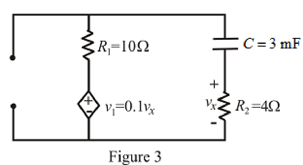
Refer to the redrawn Figure 3:

Circuit is drawn for resistor without dielectric.

As there is no independent source present in the circuit which means voltage across capacitor is also 0V.

So, value of vC(0) is 0V.

At t=0+ the capacitor does not allow sudden change in the voltage.

Therefore,

vC(0+)=vC(0)

So,

vC(0+)=0 V

The circuit diagram is redrawn as shown in Figure 4 for
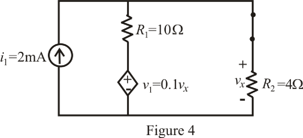
 t>0.

Loose Leaf for Engineering Circuit Analysis Format: Loose-leaf, Chapter 8, Problem 77E , additional homework tip  4

At t= the capacitor in the RC circuit is connected for long time.

So, capacitor behaves as open circuit.

The circuit diagram is redrawn as shown in Figure 5 for t=.

Loose Leaf for Engineering Circuit Analysis Format: Loose-leaf, Chapter 8, Problem 77E , additional homework tip  5

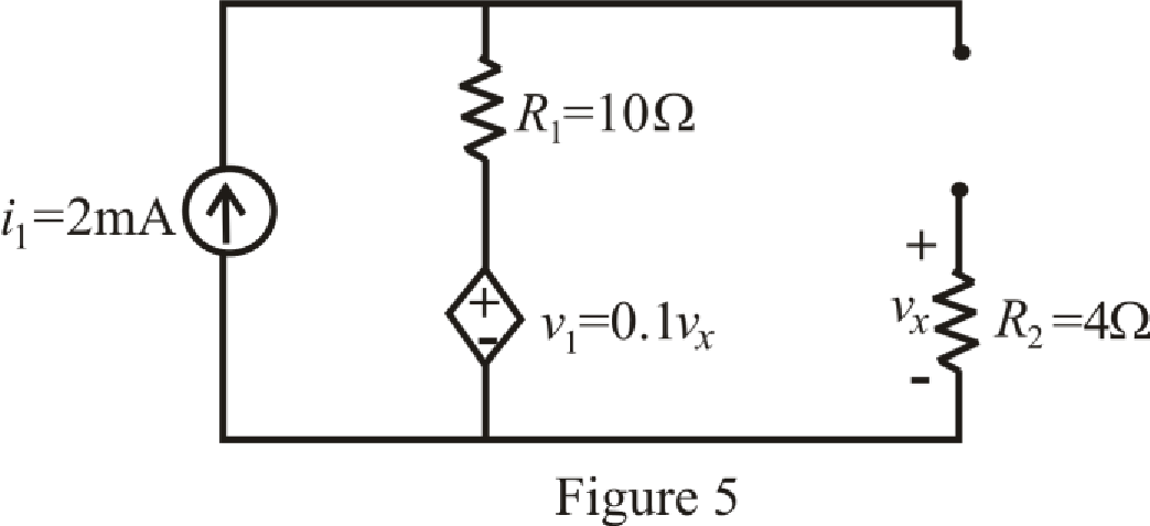
Refer to the redrawn Figure 5:

The expression for voltage v1 is as follows:

v1=0.1vx (18)

Here,

v1 is voltage in the circuit and

vx is voltage across resistor R2.

As capacitor is open circuited, current flowing through resistor R2 is 0A.

Which means value of voltage vx is 0V.

Substitute 0V for vx in equation (18):

v1=0.1(0V)=0V

The circuit diagram is redrawn as shown in Figure 6 for t=.

Loose Leaf for Engineering Circuit Analysis Format: Loose-leaf, Chapter 8, Problem 77E , additional homework tip  6

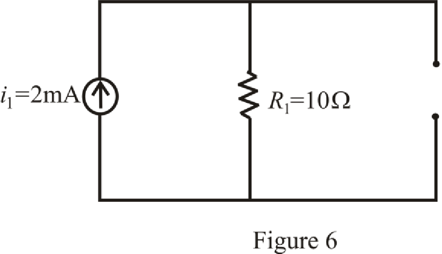
Refer to the redrawn Figure 6:

Substitute 2mA for i and 10Ω for R1 in equation (15):

v=(2mA)(10Ω)=(2×10³A)(10Ω)              {1mA=103A}=0.02V

So,

vC()=0.02V

Substitute 0.02V for vC(), 0V for vC(0+), 40.8ms for τ in equation (16):

vC(t)=0.02V+(0V0.02V)et40.8ms=0.02(1et40.8ms)V

Substitute 0.02(1et40.8ms)V for vC and 3 mF for C in equation (17):

iC=3 mFddt(0.02(1et40.8ms)V)=3 mF(0.02)(140.8mset40.8msV)

iC=1.4706et40.8msmA (19)

Substitute 200ms for t in equation (19):

iC=1.4706e200ms40.8msmA=0.01093mA

The expression for voltage vx is as follows:

vx=iCR2 (20)

Here,

vx is voltage across resistor R2,

iC is capacitor current and

R2 is the resistance in the circuit.

Substitute 0.01093mA for iC and 4Ω for R2 in equation (20):

vx=(0.01093mA)4Ω=0.04372mV

So, value of voltage vx without dielectric is 0.04372mV.

Circuit is drawn for resistor with dielectric.

The circuit diagram is redrawn as shown in Figure 7 for t<0.

Loose Leaf for Engineering Circuit Analysis Format: Loose-leaf, Chapter 8, Problem 77E , additional homework tip  7

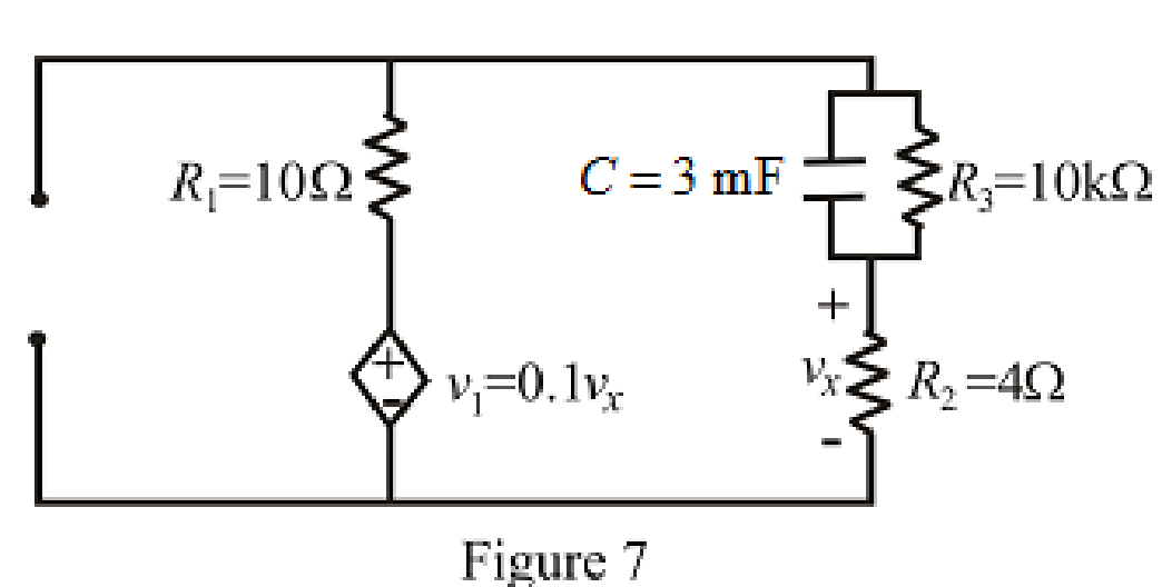
Refer to the redrawn Figure 7:

As there is no independent source present in the circuit which means voltage across capacitor is also 0V.

So, value of vC(0) is 0V.

At t=0+ the capacitor does not allow sudden change in the voltage.

Therefore,

vC(0+)=vC(0)

So,

vC(0+)=0 V

The circuit diagram is redrawn as shown in Figure 8for
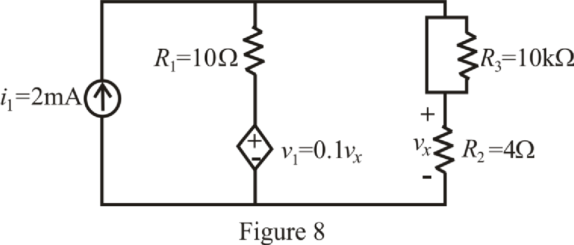
 t>0.

Loose Leaf for Engineering Circuit Analysis Format: Loose-leaf, Chapter 8, Problem 77E , additional homework tip  8

At t= the capacitor in the RC circuit is connected for long time.

So, capacitor behaves as open circuit.

The circuit diagram is redrawn as shown in Figure 9 for t=.

Loose Leaf for Engineering Circuit Analysis Format: Loose-leaf, Chapter 8, Problem 77E , additional homework tip  9

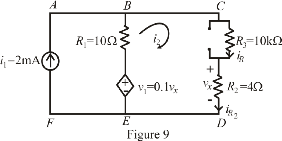
Refer to the redrawn Figure 9:

The expression for KVL in mesh FABEF is as follows:

(i1i2)R1+v1=0 (21)

Here,

i1 is current flowing in mesh FABEF,

i2 is current flowing in mesh FABEF,

R1 is resistance in the circuit and

v1 is voltage in circuit.

Substitute 2mA for i1, 10Ω for R1 and 0.1vx for v1 in equation (21):

(2mAi2)(10Ω)+0.1vx=0(2×10³Ai2)(10Ω)+0.1vx=0           {1mA=103A}

0.02V10i2+0.1vx=0 (22)

The expression for voltage vx is as follows:

vx=i2R2 (23)

Here,

vx is voltage across resistor R2,

i2 iscurrent in mesh EBCDE and

R2 is the resistance in the circuit.

Substitute 4Ω for R2 in equation (23):

vx=i2(4Ω)

Substitute 4i2 in equation (22):

0.02V10i2+0.1(4i2)=00.02V10i2+0.4(i2)=0

0.02V10.4i2=0 (24)

Rearrange equation (24) for i2:

10.4i2=0.02

Simplify for i2,

i2=1.92mA

Substitute 1.92mA for i2 and 10 for R3 in equation (15):

v=(1.92mA)(10)=(1.92×10³A)(10×103Ω)             {1mA=103A1=103Ω}=19.2V

So,

vC()=19.2V

Substitute 19.2V for vC(), 0V for vC(0+), 40.7446ms for τ in equation (16),

vC(t)=19.2V+(0V19.2V)et40.7446ms

vC(t)=19.2(1et40.7446ms)V (25)

Substitute 19.2(1et40.7446ms)V for vC and 3 mF for C in equation (17):

iC(t)=3 mFddt(19.2(1et40.7446ms)VV)=3 mF(19.2)(140.7446mset40.7446msV)

iC(t)=1.4137et40.7446msmA (26)

Substitute 200ms for t in equation (26):

iC(200ms)=1.4137e200ms40.7446msmA=0.01044mA

Substitute 200ms for t in equation (25):

vC(200ms)=19.2(1e200ms40.7446ms)V=19.2(0.993)V=19.06V

The expression for current iR is as follows:

iR(200ms)=vC(200ms)R3 (27)

Here,

iR is current flowing through resistor R3,

vC(200ms) is the voltage across the capacitor and

R3 is the resistance in the circuit.

Substitute 19.06V for vC(200ms) and 10 for R3 in equation (27):

iR=19.06V10=19.06V10×103Ω                 {1=103Ω}=0.001906A

The expression for current iR2 is as follows,

iR2=iR+iC (28)

Here,

iR is current flowing through resistor R3,

iC is capacitor current and

iR2 is current flowing through resistor R2.

Substitute 0.001906A for iR(200ms) and 0.01044mA for iC(200ms) in equation (28):

iR2(200ms)=0.001906A+0.01044mA=0.01235A

The expression for voltage vx is as follows:

vx=iR2R2 (29)

Here,

vx is voltage across resistor R2,

iR2 is current flowing through resistor R2 and

R2 is the resistance in the circuit.

Substitute 0.01235A for iR2(200ms) and 4Ω for R2 in equation (29),

vx=(0.01235A)4Ω=0.04938mV

So value of voltage vx with dielectric is 0.04938mV.

The expression for percentage change in voltage vx with dielectric resistor is as follows:

Δvx=vx2vx1vx2×100 (14)

Here,

Δvx is percentage change in voltage vx,

vx1 isvalue of voltage vx without dielectric and

vx2 isvalue of voltage vx with dielectric.

Substitute 40.8ms for vx1 and 40.7446ms for vx2 in equation (14):

Δvx=0.04938mV0.04372mV0.04938mV×100=0.00566mV0.04938mV×100=11.46%

Conclusion:

Thus, value of voltage vx without dielectric is 0.04372mV, value of voltage vx with dielectric is 0.04938mV and value of percentage change in voltage vx is 11.46%.

Want to see more full solutions like this?

Subscribe now to access step-by-step solutions to millions of textbook problems written by subject matter experts!
Students have asked these similar questions
Calculate initial conditions for inductor current and capacitor voltage in circuit presented in Fig. 8.3. Assume: L=1H, C=0.5F, R=1Ω, e(t) = 10 2 sin(t + 45 ) V, i(t) = 2sin(t − 45 ) A.
Suppose the input to the circuit is a damped ramp of the form Kte−100t V. Find the largest value of K such that the inductor current does not exceed the 40 mA current rating
The switch in Fig. 8.73 is moved from A to B at t = 0 after being at A for a long time. This places the two capacitors in series, thus allowing equal and opposite de voltages to be trapped on the capacitors   (d) Find vr(t), t > 0. (e) Find i(t). (f) Find vi(t) and v2(t) from i(t) and the initial values. (g) Show that the stored energy at i = 0 plus the total energy dissipated in the 20 kS2 resistor is equal to the energy stored in the capacitors at t = 0

Chapter 8 Solutions

Loose Leaf for Engineering Circuit Analysis Format: Loose-leaf

Ch. 8.7 - Prob. 11PCh. 8.7 - The voltage source 60 40u(t) V is in series with...Ch. 8.7 - Prob. 13PCh. 8.8 - Prob. 14PCh. 8.8 - Prob. 15PCh. 8 - A source-free RC circuit has R = 4 k and C = 22 F,...Ch. 8 - A source-free RC circuit has v(0) = 12 V and R =...Ch. 8 - The resistor in the circuit of Fig. 8.51 has been...Ch. 8 - Prob. 4ECh. 8 - Prob. 5ECh. 8 - Prob. 6ECh. 8 - Prob. 7ECh. 8 - Prob. 8ECh. 8 - Prob. 9ECh. 8 - The switch in Fig. 8.56 has been closed for a long...Ch. 8 - For the circuit in Fig. 8.56, find (a) the total...Ch. 8 - Design a capacitor-based circuit that can achieve...Ch. 8 - (a) Graph the function f (t) = 10e2t over the...Ch. 8 - The current i(t) flowing through a 1 k resistor is...Ch. 8 - Radiocarbon dating has a similar exponential time...Ch. 8 - For the circuit of Fig. 8.4, compute the time...Ch. 8 - Design a circuit which will produce a current of 1...Ch. 8 - Prob. 18ECh. 8 - Prob. 19ECh. 8 - Referring to the circuit shown in Fig. 8.11,...Ch. 8 - Prob. 21ECh. 8 - With the assumption that the switch in the circuit...Ch. 8 - The switch in Fig. 8.57 has been closed since...Ch. 8 - The switch in the circuit of Fig. 8.58 has been...Ch. 8 - Assuming the switch initially has been open for a...Ch. 8 - (a) Obtain an expression for v(t), the voltage...Ch. 8 - For the circuit of Fig. 8.61, determine ix, iL,...Ch. 8 - Prob. 28ECh. 8 - Prob. 29ECh. 8 - Prob. 30ECh. 8 - Prob. 31ECh. 8 - (a) Obtain an expression for vx as labeled in the...Ch. 8 - Prob. 33ECh. 8 - Prob. 34ECh. 8 - Prob. 35ECh. 8 - Prob. 36ECh. 8 - Prob. 37ECh. 8 - The switch in Fig. 8.70 is moved from A to B at t...Ch. 8 - Prob. 39ECh. 8 - Prob. 40ECh. 8 - Evaluate the following functions at t = 1, 0, and...Ch. 8 - Prob. 42ECh. 8 - Prob. 43ECh. 8 - Prob. 44ECh. 8 - You can use MATLAB to represent the unit-step...Ch. 8 - With reference to the circuit depicted in Fig....Ch. 8 - For the circuit given in Fig. 8.75, (a) determine...Ch. 8 - Prob. 48ECh. 8 - Prob. 49ECh. 8 - You build a portable solar charging circuit...Ch. 8 - The switch in the circuit of Fig. 8.78 has been...Ch. 8 - The switch in the circuit of Fig. 8.78 has been...Ch. 8 - Prob. 53ECh. 8 - Prob. 54ECh. 8 - Prob. 55ECh. 8 - For the circuit represented in Fig. 8.82, (a)...Ch. 8 - Prob. 58ECh. 8 - Prob. 59ECh. 8 - For the circuit given in Fig. 8.85, (a) determine...Ch. 8 - The circuit depicted in Fig. 8.86 contains two...Ch. 8 - Prob. 62ECh. 8 - Prob. 63ECh. 8 - A series RL circuit has a voltage that steps from...Ch. 8 - For the two-source circuit of Fig. 8.89, note that...Ch. 8 - (a) Obtain an expression for iL as labeled in Fig....Ch. 8 - Obtain an expression for i(t) as labeled in the...Ch. 8 - Obtain an expression for i1 as indicated in Fig....Ch. 8 - Plot the current i(t) in Fig. 8.93 if (a) R = 10 ;...Ch. 8 - A dc motor can be modeled as a series RL circuit...Ch. 8 - Prob. 71ECh. 8 - Prob. 72ECh. 8 - A series RC sequentially switched circuit has R =...Ch. 8 - Refer to the circuit of Fig. 8.95, which contains...Ch. 8 - In the circuit of Fig. 8.95, a 3 mF capacitor is...Ch. 8 - Prob. 78E
Knowledge Booster
Background pattern image
Electrical Engineering
Learn more about
Need a deep-dive on the concept behind this application? Look no further. Learn more about this topic, electrical-engineering and related others by exploring similar questions and additional content below.
Similar questions
SEE MORE QUESTIONS
Recommended textbooks for you
Text book image
Introductory Circuit Analysis (13th Edition)
Electrical Engineering
ISBN:9780133923605
Author:Robert L. Boylestad
Publisher:PEARSON
Text book image
Delmar's Standard Textbook Of Electricity
Electrical Engineering
ISBN:9781337900348
Author:Stephen L. Herman
Publisher:Cengage Learning
Text book image
Programmable Logic Controllers
Electrical Engineering
ISBN:9780073373843
Author:Frank D. Petruzella
Publisher:McGraw-Hill Education
Text book image
Fundamentals of Electric Circuits
Electrical Engineering
ISBN:9780078028229
Author:Charles K Alexander, Matthew Sadiku
Publisher:McGraw-Hill Education
Text book image
Electric Circuits. (11th Edition)
Electrical Engineering
ISBN:9780134746968
Author:James W. Nilsson, Susan Riedel
Publisher:PEARSON
Text book image
Engineering Electromagnetics
Electrical Engineering
ISBN:9780078028151
Author:Hayt, William H. (william Hart), Jr, BUCK, John A.
Publisher:Mcgraw-hill Education,
ENA 9.2(1)(En)(Alex) Sinusoids & Phasors - Explanation with Example 9.1 ,9.2 & PP 9.2; Author: Electrical Engineering Academy;https://www.youtube.com/watch?v=vX_LLNl-ZpU;License: Standard YouTube License, CC-BY
Electrical Engineering: Ch 10 Alternating Voltages & Phasors (8 of 82) What is a Phasor?; Author: Michel van Biezen;https://www.youtube.com/watch?v=2I1tF3ixNg0;License: Standard Youtube License