
Concept explainers
Videos
The principal stresses at point A.
Answer to Problem 1RP
The principal stresses at point A
Explanation of Solution
Calculate the normal stress
Here,
Sketch the internal forces and moment in free body diagram at point A as shown in Figure 1.
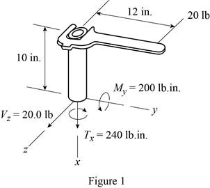
Apply Equilibrium equations to find the value of moment at point A.
Sum of moments in y-direction is equal to 0.
Sum of moments in x-direction is equal to 0.
Sum of forces in z-direction is equal to 0.
Find the moment of inertia of the section
Outer radius of the pipe is 1.5 in. and the inner radius of the pipe is 1.375 in.
Find the polar moment of inertia of the section
Sketch the cross section at point A as shown in Figure 2.
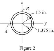
Find the first moment of area at point A
Here,
Refer to Figure 2.
Substitute
Find the shear stress
Substitute
Sketch the state of stress at point A as shown in Figure 3.
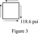
Refer to Figure 3.
The value of normal stresses are
The value of shear stress is
Find the principal stresses
Substitute
Therefore, the principal stresses
Want to see more full solutions like this?
Chapter 9 Solutions
MECHANICS OF MATERIALS


- Determine the shortest distance d to the edge of the plate at which the force P can be applied so that it produces no compressive stresses in the plate at section a–a. The plate has a thickness of 10 mm and P acts along the centerline of this thickness.arrow_forwardThe tank of the air compressor is subjected to an internal pressure of 90 psi. If the inner diameter of the tank is 22 in., and the wall thickness is 0.25 in., determine the stress components acting at point A. Draw a volume element of the material at this point, and show the results on the element.arrow_forwardDetermine the maximum distance d to the edge of the plate at which the force P can be applied so that it produces no compressive stresses on the plate at section a–a. The plate has a thickness of 20 mm and P acts along thecenterline of this thickness.arrow_forward
- The wide-flange beam is subjected to the 50-kN force. Determine the principal stresses in the beam at point A located on the web at the bottom of the upper flange. Although it is not very accurate, use the shear formula tocalculate the shear stress.arrow_forwardAir pressure in the cylinder is increased by exerting forces P = 2 kN on the two pistons, each having a radius of 45 mm. If the cylinder has a wall thickness of 2 mm, determine the state of stress in the wall of the cylinder.arrow_forwardThe bolt is fixed to its support at C. If a force of 18 lb is applied to the wrench to tighten it, determine the principal stresses and the absolute maximum shear stress in the bolt shank at point A. Represent the results on an elementlocated at this point. The shank has a diameter of 0.25 in.arrow_forward
- The clamp presses the smooth surface at E when tightening the screw. If the tension in the bolt is 40 kN, determine the principal stress at points A and B and show the results on the elements located at each of these points. The cross-sectional area at A and B is shown in the adjacent figure. 300 mm 50 mm 30 mm 100 mm B 25 mm A 100 mm -50 mmarrow_forwardThe propeller shaft of the tugboat is subjected to the compressive force and torque shown. If the shaft has an inner diameter of 100 mm and an outer diameter of 150 mm, determine the principal stresses at a point A located on the outer surface.arrow_forwardThe steel pipe in (Figure 1) has an inner diameter of 3.41 in and an outer diameter of 3.66 in. If it is fixed at C and subjected to the horizontal 60-lb force acting on the handle of the pipe wrench at its end, determine the principal stresses in the pipe at point A, which is located on the outer surface of the pipe.arrow_forward
- The box beam is subjected to the 26-kN force that is applied at the center of its width, 75 mm from each side. Determine the principal stresses at point A and show the results in an element located at this point. Use the shear formula to calculate the shear stress.arrow_forwardThe rotor shaft of the helicopter is subjected to the tensile force and torque shown when the rotor blades provide the lifting force to suspend the helicopter at midair. If the shaft has a diameter of 6 in., determine the principal stresses and maximum in-plane shear stress at a point located on the surface of the shaft.arrow_forwardThe copper pipe has an outer diameter of 2.50 in. and an inner diameter of 2.30 in. If it is tightly secured to the wall and three torques are applied to it, determine the shear stress developed at points A and B. These points lie on the pipe’s outer surface. Sketch the shear stress on volume elements located at A and B.arrow_forward
 Elements Of ElectromagneticsMechanical EngineeringISBN:9780190698614Author:Sadiku, Matthew N. O.Publisher:Oxford University Press
 Mechanics of Materials (10th Edition)Mechanical EngineeringISBN:9780134319650Author:Russell C. HibbelerPublisher:PEARSON
 Thermodynamics: An Engineering ApproachMechanical EngineeringISBN:9781259822674Author:Yunus A. Cengel Dr., Michael A. BolesPublisher:McGraw-Hill Education
 Control Systems EngineeringMechanical EngineeringISBN:9781118170519Author:Norman S. NisePublisher:WILEY
 Mechanics of Materials (MindTap Course List)Mechanical EngineeringISBN:9781337093347Author:Barry J. Goodno, James M. GerePublisher:Cengage Learning
 Engineering Mechanics: StaticsMechanical EngineeringISBN:9781118807330Author:James L. Meriam, L. G. Kraige, J. N. BoltonPublisher:WILEY