
Microelectronics: Circuit Analysis and Design
4th Edition
ISBN: 9780073380643
Author: Donald A. Neamen
Publisher: McGraw-Hill Companies, The
expand_more
expand_more
format_list_bulleted
Videos
Textbook Question
Chapter 9, Problem 9.47P
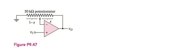
The circuit shown in Figure P9.47 can be used as a variable noninverting amplifier. The circuit uses a
Expert Solution & Answer
Want to see the full answer?
Check out a sample textbook solution
Students have asked these similar questions
Determine the closed-loop voltage gain of the circuit shown in the figure assumingan ideal op amp
Draw the circuit diagram of the basic inverting amplifier configuration. Give an expression for the closed-loop voltage gain of the circuit in terms of the resistances, assuming an ideal op amp. Give expressions for the input impedance and output impedance of the circuit.
Draw and interpret the gain-frequency graph of the op-amp circuit given in the figure.
Chapter 9 Solutions
Microelectronics: Circuit Analysis and Design
Ch. 9 - Design an ideal inverting op-amp circuit such that...Ch. 9 - Design an ideal inverting op-amp circuit with a...Ch. 9 - (a) An inverting op-amp circuit is to be designed...Ch. 9 - (a) Design an ideal inverting op-amp circuit such...Ch. 9 - Prob. 9.2TYUCh. 9 - Consider an inverting op-amp circuit as shown in...Ch. 9 - (a) Design an inverting summing amplifier that...Ch. 9 - Consider an ideal summing amplifier as shown in...Ch. 9 - Design the summing amplifier in Figure 9.14 to...Ch. 9 - (a) Design a noninverting amplifier such that the...
Ch. 9 - The noninverting op-amp in Figure 9.15 has a...Ch. 9 - Use superposition to determine the output voltage...Ch. 9 - Consider the voltage-to-current converter shown in...Ch. 9 - Consider the difference amplifier in Figure...Ch. 9 - In the difference amplifier shown in Figure...Ch. 9 - For the instrumentation amplifier in Figure 9.26,...Ch. 9 - An integrator with input and output voltages that...Ch. 9 - A current source has an output impedance of...Ch. 9 - Design the voltage-to-current converter shown in...Ch. 9 - All parameters associated with the instrumentation...Ch. 9 - Design the instrumentation amplifier in Figure...Ch. 9 - An integrator is driven by the series of pulses...Ch. 9 - Consider the summing op-amp in Figure 9.40. Let...Ch. 9 - Consider the bridge circuit in Figure 9.46. The...Ch. 9 - The resistance R in the bridge circuit in Figure...Ch. 9 - Describe the ideal op-amp model and describe the...Ch. 9 - Prob. 2RQCh. 9 - Describe the operation and characteristics of the...Ch. 9 - What is the concept of virtual ground?Ch. 9 - What is the significance of a zero output...Ch. 9 - When a finite op-amp gain is taken into account,...Ch. 9 - Prob. 7RQCh. 9 - Describe the operation and characteristics of the...Ch. 9 - Describe the voltage follower. What are the...Ch. 9 - What is the input resistance of an ideal...Ch. 9 - Prob. 11RQCh. 9 - Describe the operation and characteristics of an...Ch. 9 - Describe the operation and characteristics of an...Ch. 9 - Describe the operation and characteristics of an...Ch. 9 - Assume an op-amp is ideal, except for having a...Ch. 9 - The op-amp in the circuit shown in Figure P9.2 is...Ch. 9 - An op-amp is in an open-loop configuration as...Ch. 9 - Consider the equivalent circuit of the op-amp...Ch. 9 - Consider the ideal inverting op-amp circuit shown...Ch. 9 - Assume the op-amps in Figure P9.6 are ideal. Find...Ch. 9 - Consider an ideal inverting op-amp with R2=100k...Ch. 9 - (a) Design an inverting op-amp circuit with a...Ch. 9 - Consider an ideal op-amp used in an inverting...Ch. 9 - Consider the inverting amplifier shown in Figure...Ch. 9 - (a) Design an inverting op-amp circuit with a...Ch. 9 - (a) Design an inverting op-amp circuit such that...Ch. 9 - (a) In an inverting op-amp circuit, the nominal...Ch. 9 - (a) The input to the circuit shown in Figure P9.14...Ch. 9 - Design an inverting amplifier to provide a nominal...Ch. 9 - The parameters of the two inverting op-amp...Ch. 9 - Design the cascade inverting op-amp circuit in...Ch. 9 - Design an amplifier system with three inverting...Ch. 9 - Consider the circuit shown in Figure P9.19. (a)...Ch. 9 - The inverting op-amp shown in Figure 9.9 has...Ch. 9 - (a)An op-amp with an open-loop gain of Aod=7103 is...Ch. 9 - (a) For the ideal inverting op-amp circuit with...Ch. 9 - An ideal inverting op-amp circuit is to be...Ch. 9 - For the op-amp circuit shown in Figure P9.25,...Ch. 9 - The inverting op-amp circuit in Figure 9.9 has...Ch. 9 - (a) Consider the op-amp circuit in Figure P9.27....Ch. 9 - The circuit in Figure P9.28 is similar to the...Ch. 9 - Consider the ideal inverting summing amplifier in...Ch. 9 - (a) Design an ideal inverting summing amplifier to...Ch. 9 - Design an ideal inverting summing amplifier to...Ch. 9 - Consider the summing amplifier in Figure 9.14 with...Ch. 9 - The parameters for the summing amplifier in Figure...Ch. 9 - (a) Design an ideal summing op-amp circuit to...Ch. 9 - An ideal three-input inverting summing amplifier...Ch. 9 - A summing amplifier can be used as a...Ch. 9 - Consider the circuit in Figure P9.38. (a) Derive...Ch. 9 - Consider the summing amplifier in Figure 9.14(a)....Ch. 9 - Consider the ideal noninverting op-amp circuit in...Ch. 9 - (a) Design an ideal noninverting op-amp circuit...Ch. 9 - Consider the noninverting amplifier in Figure...Ch. 9 - For the circuit in Figure P9.43, the input voltage...Ch. 9 - Determine vO as a function of vI1 and vI2 for the...Ch. 9 - Consider the ideal noninverting op-amp circuit in...Ch. 9 - (a) Derive the expression for the closed-loop...Ch. 9 - The circuit shown in Figure P9.47 can be used as a...Ch. 9 - (a) Determine the closed-loop voltage gain...Ch. 9 - For the amplifier in Figure P9.49, determine (a)...Ch. 9 - Consider the voltage-follower circuit in Figure...Ch. 9 - (a) Consider the ideal op-amp circuit shown in...Ch. 9 - (a) Assume the op-amp in the circuit in Figure...Ch. 9 - Prob. 9.53PCh. 9 - A current-to-voltage converter is shown in Figure...Ch. 9 - Figure P9.55 shows a phototransistor that converts...Ch. 9 - The circuit in Figure P9.56 is an analog voltmeter...Ch. 9 - Consider the voltage-to-current converter in...Ch. 9 - The circuit in Figure P9.58 is used to drive an...Ch. 9 - Figure P9.59 is used to calculate the resistance...Ch. 9 - Consider the op-amp difference amplifier in Figure...Ch. 9 - Consider the differential amplifier shown in...Ch. 9 - Consider the differential amplifier shown in...Ch. 9 - Let R=10k in the differential amplifier in Figure...Ch. 9 - Consider the circuit shown in Figure P9.64. (a)...Ch. 9 - The circuit in Figure P9.65 is a representation of...Ch. 9 - Consider the adjustable gain difference amplifier...Ch. 9 - Assume the instrumentation amplifier in Figure...Ch. 9 - Consider the circuit in Figure P9.68. Assume ideal...Ch. 9 - Consider the circuit in Figure P969. Assume ideal...Ch. 9 - The instrumentation amplifier in Figure 9.26 has...Ch. 9 - Design the instrumentation amplifier in Figure...Ch. 9 - All parameters associated with the instrumentation...Ch. 9 - The parameters in the integrator circuit shown in...Ch. 9 - Consider the ideal op-amp integrator. Assume the...Ch. 9 - The circuit in Figure P9.75 is a first-order...Ch. 9 - (a) Using the results of Problem 9.75, design the...Ch. 9 - The circuit shown in Figure P9.77 is a first-order...Ch. 9 - (a) Using the results of Problem 9.77, design the...Ch. 9 - Prob. 9.79PCh. 9 - Consider the circuit in Figure 9.35. The diode...Ch. 9 - In the circuit in Figure P9.81, assume that Q1 and...Ch. 9 - Consider the circuit in Figure 9.36. The diode...Ch. 9 - Design an op-amp summer to produce the output...Ch. 9 - Design an op-amp summer to produce an output...Ch. 9 - Design a voltage reference source as shown in...Ch. 9 - Consider the voltage reference circuit in Figure...Ch. 9 - Consider the bridge circuit in Figure P9.87. The...Ch. 9 - Consider the bridge circuit in Figure 9.46. The...
Knowledge Booster


Learn more about
Need a deep-dive on the concept behind this application? Look no further. Learn more about this topic, electrical-engineering and related others by exploring similar questions and additional content below.Similar questions
- Draw the circuit diagram of the basic noninverting amplifier configuration. Give an expression for the closed-loop voltage gain of the circuit in terms of the resistances, assuming an ideal op amp. Give expressions for the input impedance and output impedance of the circuit.arrow_forwardPlease answer this two part question A) It is known that when an Op-amp is operated using the negative feedbackconfiguration, the output impedance reduces. Derive an expression that proves this. B) It is known that when an Op-amp is operated using the positive feedbackconfiguration, the output impedance increase. Derive an expression that proves this.arrow_forwardassume ideal op-amp Find the center frequency, BW, & the gainarrow_forward
- Based on the plots of Vin and Vout, is the op-amp consistent with its inverting function? Justify your answer.arrow_forwarda) What is an Op-Amp, and how is it used? b) What is the equivalent circuit model for an op-amp? c) What is negative feedback, and why is it used in Op Amp Circuits?arrow_forwardThe op amp in the circuit of Figure is ideal.a) What op amp circuit configuration is this?b) Find ?0 in terms of ??.c) Find the range of values for ?? such that ?0 does not saturate and the op ampremains in its linear region of operation.arrow_forward
- An inverting op – amplifier stage is designed with an input resistance of 5 KΩ and feedback resistance of 10 KΩ. The load resistance is 100 Ω with DC gain of 5x10^4 . The output internal resistance is 500 Ω while the input impedance is infinity, assuming an input voltage of 1.5 volts, calculate the following ?a) The AC gain ?b) The output voltage ?c) The looking back resistance ?arrow_forwardQuestion 3: Please write answers to all parts of the question in the separate dot points as shown What is the circuit called? Discuss all components including voltage sources. Which components determine the closed-loop gain of the circuit? Describe the slew-rate of the op-amp. Describe the Common-Mode-Rejection ratio of the op-amp? What is the unity gain bandwidth? Describe the gain bandwidth product (GBP). Describe the GBP relationship between the break (critical) frequency and the gain? What two methods calculate the max frequency? If one produces a higher value of maximum frequency than the other, which would you use as the maximum frequency?arrow_forwarda) Draw the circuit diagram of an op-amp voltage follower. b) What value is its voltage gain? c) What is the input impedance? What is the output impedance?arrow_forward
- Draw the circuit diagram of an op-amp voltage follower. What value is its voltage gain? Input impedance? Output impedance?arrow_forwardA noninverting amplifier is being designed to have a closed-loop gain of 36 dB. What op-amp gain is required to have the gain error less than 0.15 percent?arrow_forwardSuppose the op amp shown has an fT of 2 MHz. What is the phase margin of the amplifier?arrow_forward
arrow_back_ios
SEE MORE QUESTIONS
arrow_forward_ios
Recommended textbooks for you
 Introductory Circuit Analysis (13th Edition)Electrical EngineeringISBN:9780133923605Author:Robert L. BoylestadPublisher:PEARSON
 Delmar's Standard Textbook Of ElectricityElectrical EngineeringISBN:9781337900348Author:Stephen L. HermanPublisher:Cengage Learning
 Programmable Logic ControllersElectrical EngineeringISBN:9780073373843Author:Frank D. PetruzellaPublisher:McGraw-Hill Education
 Fundamentals of Electric CircuitsElectrical EngineeringISBN:9780078028229Author:Charles K Alexander, Matthew SadikuPublisher:McGraw-Hill Education
 Electric Circuits. (11th Edition)Electrical EngineeringISBN:9780134746968Author:James W. Nilsson, Susan RiedelPublisher:PEARSON
 Engineering ElectromagneticsElectrical EngineeringISBN:9780078028151Author:Hayt, William H. (william Hart), Jr, BUCK, John A.Publisher:Mcgraw-hill Education,
Introductory Circuit Analysis (13th Edition)
Electrical Engineering
ISBN:9780133923605
Author:Robert L. Boylestad
Publisher:PEARSON
Delmar's Standard Textbook Of Electricity
Electrical Engineering
ISBN:9781337900348
Author:Stephen L. Herman
Publisher:Cengage Learning
Programmable Logic Controllers
Electrical Engineering
ISBN:9780073373843
Author:Frank D. Petruzella
Publisher:McGraw-Hill Education
Fundamentals of Electric Circuits
Electrical Engineering
ISBN:9780078028229
Author:Charles K Alexander, Matthew Sadiku
Publisher:McGraw-Hill Education
Electric Circuits. (11th Edition)
Electrical Engineering
ISBN:9780134746968
Author:James W. Nilsson, Susan Riedel
Publisher:PEARSON
Engineering Electromagnetics
Electrical Engineering
ISBN:9780078028151
Author:Hayt, William H. (william Hart), Jr, BUCK, John A.
Publisher:Mcgraw-hill Education,
Current feedback amplifiers - Overview and compensation techniques; Author: Texas Instruments;https://www.youtube.com/watch?v=2WZotqHiaq8;License: Standard Youtube License