
Videos
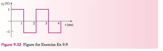
An integrator with input and output voltages that are zero at
(a)
The value of the output voltage for different time interval.
Answer to Problem 9.9EP
Thevalue of the output voltage for the different time interval is
Explanation of Solution
Calculation:
The given diagram is shown in Figure 1
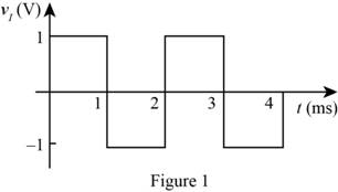
From the above waveform the expression for the voltage is given by,
Mark the values and draw the integrated op-amp circuit.
The required diagram is shown in Figure 2
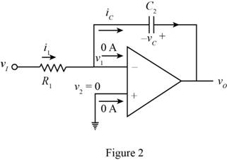
Apply KVL at the feedback loop.
Substitute
The conversion from
The conversion from
The conversion from
The conversion from
The conversion from
The conversion from
The conversion from
The conversion from
Apply KCL at the inverting terminal.
Substitute
Substitute
The expression for the output voltage for the time
Substitute
The expression for the output voltage for the time
The expression for the output voltage for the time
Substitute
The expression for the output voltage for the time
The value of the voltage output voltage for different time interval is given by,
Conclusion:
Therefore, the value of the output voltage for the different time interval is
(b)
The value of the output voltage for different time interval.
Answer to Problem 9.9EP
Thevalue of the output voltage for the different time interval is
Explanation of Solution
Calculation:
The expression for the output voltage for the time
Substitute
The expression for the output voltage for the time
The expression for the output voltage for the time
Substitute
The expression for the output voltage for the time
The value of the voltage output voltage for different time interval is given by,
Conclusion:
Therefore, the value of the output voltage for the different time interval is
Want to see more full solutions like this?
Chapter 9 Solutions
Microelectronics: Circuit Analysis and Design


- how will the complex convolution be evaluated? DSP subjectarrow_forwardAn exponential signal has initial value Vi=v(0)=-3[V], final value Vf=(∞)=6[V], and a time constant of 10s. Determine: a) the equation for v(t) b) Graph the function for 0≤t≤100 sec, together with a table of values at 10s (or less) time intervals.arrow_forwardA car was ignited & a signal from the engine i.e a(z) was passed through a cascade of 2 passive RC lowpass filters to generate an output signal, b(z).a.Show a differential equation derivation to describe the systemb.Make a sketch utilizing circuit diagramc.Mention if the RC system in question above isi.Time in-variant / Time variant ii.Non linear / lineariii.Non-invertible / Invertibleiv. Non-causal / Causal v. Have no memory / Have memory sytems.d. d2b(z)/dz2 + 3(db(z)/dz) +2b(z) = 3(da(z)/dz) +2a(z)Let's assume that the d.e(differential equation) above is that which is characterised by the RC system in the main question above.Where a(z) & b(z) is the input & output of the RC system respectively.Considering an impulse of a(z)=δ(z) is applied to the system, determine the output b(z) of the systemarrow_forward
- Sketch the root locus of the system whose open loop transfer function is G(s)=k/s(s+4)(s+6). Find the value of k so that damping ratio of closed loop system is 0.6.arrow_forwardconsider the electrical circuit shown in the diagram below where R1=R2=0.5 ohms L=1 Henry C=1 farad. (These values are UNREALISTIC , but they are here for ease of calculation) For this problem assume that implies NULL initial conditions (all the initial conditions are 0) a) what is the transfer function H(s) =Vo(s)/Vi(s) for the system ? b) what is the impulse response function h(t), for this circuit?arrow_forwardConsider the given circuit with vi=3V, R1=20K, Rf=50K, R2=10K, R3=20K, C=2μF. Assuming that the capacitor is an open circuit, and vo=-5V, determine the Thevenin equivalent of vo.arrow_forward
- A hard disk drive (HDD) is an electro-mechanical data storage device that stores and retrieves digital data using magnetic storage and one or more rigid rapidly rotating platters coated with magnetic material. Figure 1 shows a simplified block diagram of a HDD. For analysis purposes, given gain K=30 and G(s)=1 / s(s+4) determine the open-loop and closed loop poles of the HDD and plot these separately in the S-Plane. Also discuss the stability using two different approaches.arrow_forwardAn ideal AC voltage source E drives an RCL series circuit. The source supplies a voltage U and frequency f. The source has a built-in resistance of R56. The components of the resonant circuit are a coil with inductance L1 and series resistance RL, a capacitor C, and a damping resistor R. The coil L1 is coupled to a secondary coil L2 by the mutual inductance M2. In the primary circuit, we measure the voltage drop UA across R and C, and in the secondary circuit, the induced voltage UB across the coil L2. Question Determine an expression for the mutual inductance M2.arrow_forwardThe op amp circuit shown is ideal. The values for the circuit are as follows:+VCC = 12.0V, -VCC = -10.0V, Ra = 9.00Ω, Rb = 30.0Ω, Rc = 42.0Ω, Rd = 4.00Ω, Re = 32.0Ω. Write a KCL equation at node n. Solve for the output voltage vout as a function of the inputs va and vb. If input va=2.00V and output vout =10.0V, then solve for input vb. If inputs va=8.00V and vb=5.00V, then solve for the power absorbed by Rb. If input va=4.00V, then solve for the range of input vb such that the amplifier does not saturate.arrow_forward
- 7 A system is described (characterized) by its impulse response or by its ...?arrow_forward1a) A circuit has a resonant frequency of 440 kHz and a system Q of 30. Determine the bandwidth and the approximate values for f1 and f2. b) Find the Qcoil and coil resistance of a 150 μH inductor at 100 kHz using device curve A. c) A certain 75 μH inductor is described by curve B. Determine the equivalent parallel inductor/resistor combination at 1 MHz. d) Consider a series circuit consisting of a 2 nF capacitor, an ideal 33 μH inductor and a 5 Ω resistor. Determine the resonant frequency, system Q, and bandwidth.arrow_forwardFind for the following circuit(a) Calculate the neper frequency, a and resonant radian frequency, wo of the circuit.(b) Categorize the response of the circuit of either overdamped or underdamped and solve the value of resistance, R that can cause the response to be critically damped? (c) Determine the expression of V (t) for t ≥ 0.arrow_forward
 Introductory Circuit Analysis (13th Edition)Electrical EngineeringISBN:9780133923605Author:Robert L. BoylestadPublisher:PEARSON
 Delmar's Standard Textbook Of ElectricityElectrical EngineeringISBN:9781337900348Author:Stephen L. HermanPublisher:Cengage Learning
 Programmable Logic ControllersElectrical EngineeringISBN:9780073373843Author:Frank D. PetruzellaPublisher:McGraw-Hill Education
 Fundamentals of Electric CircuitsElectrical EngineeringISBN:9780078028229Author:Charles K Alexander, Matthew SadikuPublisher:McGraw-Hill Education
 Electric Circuits. (11th Edition)Electrical EngineeringISBN:9780134746968Author:James W. Nilsson, Susan RiedelPublisher:PEARSON
 Engineering ElectromagneticsElectrical EngineeringISBN:9780078028151Author:Hayt, William H. (william Hart), Jr, BUCK, John A.Publisher:Mcgraw-hill Education,