
Concept explainers
Videos
For the beam and loading shown, (a) express the magnitude and location of the maximum deflection in terms of w0, L, E, and I. (b) Calculate the value of the maximum deflection, assuming that beam AB is a W18 × 50 rolled shape and that w0= 4.5 kips/ft, L = 18 ft, and E = 29 ×106 psi.
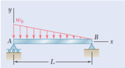
Fig. P9.11
(a)
The magnitude and location of the maximum deflection in terms of
Answer to Problem 11P
The location of the maximum deflection
The magnitude and location of the maximum deflection in terms of
Explanation of Solution
Given that:
The length (L) of the beam is
The load
The young’s modulus E is
Calculation:
Sketch the free body diagram of beam as shown in Figure 1.
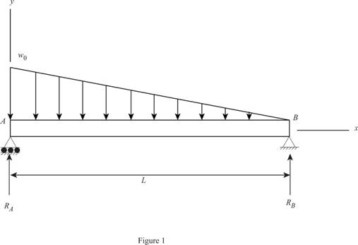
Find the reactions of the beam.
Take the moment at B.
Find the reaction at B.
Take the section 1-1 at x distance from A as shown in Figure 2.
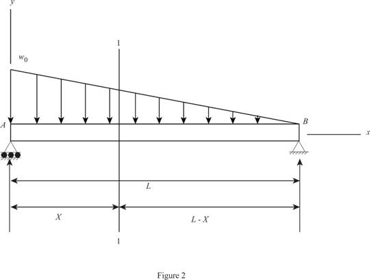
Consider a section
Sketch the section x-x as shown in Figure 3.
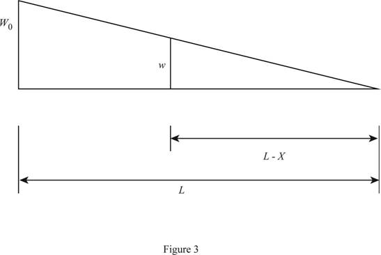
Calculate the intensity of loading w at the section x using similar triangle method as shown below:
Find the shear force using the expression as follows:
Find the shear force using integration:
Find the moment using the relation as follows:
Apply the boundary conditions:
When
When
Substitute 0 for
Write the moment Equation:
Substitute
Integrate the Equation (2).
Integrate the Equation (3).
Apply the boundary condition in
At
Find the
Substitute 0 for x and 0 for
Apply the boundary condition in
At
Find the
Substitute 0 for x and 0 for
Substitute
Differentiate with respect to x in Equation (5).
To find the location of maximum deflection:
Consider the function
Differentiate with respect to z in Equation (7).
Find the value z using Newton-Raphson method as follows:
Show the calculated values of
| 0.22 | -0.01583 | 0.050908 | 0.53100 |
| 0.24 | -0.01479 | 0.053504 | 0.51639 |
| 0.26 | -0.01369 | 0.055796 | 0.50544 |
| 0.28 | -0.01256 | 0.057792 | 0.49730 |
| 0.3 | -0.01138 | 0.0595 | 0.49134 |
| 0.32 | -0.01018 | 0.060928 | 0.48708 |
| 0.34 | -0.00895 | 0.062084 | 0.48415 |
| 0.36 | -0.0077 | 0.062976 | 0.48224 |
| 0.38 | -0.00643 | 0.063612 | 0.48111 |
| 0.4 | -0.00516 | 0.064 | 0.48056 |
| 0.42 | -0.00387 | 0.064148 | 0.48039 |
| 0.44 | -0.00259 | 0.064064 | 0.48045 |
| 0.46 | -0.00131 | 0.063756 | 0.48059 |
| 0.48 | -4.2E-05 | 0.063232 | 0.4807 |
| 0.5000 | 0.0012 | 0.0625 | 0.4806 |
| 0.52 | 0.002456 | 0.061568 | 0.48010 |
Refer to table: 1.
The value of
Find the value of
Substitute
Therefore, he magnitude of the maximum deflection in terms of
Therefore, the location of maximum deflection is
(b)
The value of maximum deflection.
Answer to Problem 11P
The value of maximum deflection is
Explanation of Solution
Calculation:
Convert
The rolled shape section
The value of
Find the maximum deflection using the relation:
Substitute
Thus, the value of maximum deflection is
Want to see more full solutions like this?
Chapter 9 Solutions
Mechanics of Materials, CE3110


- https://www.chegg.com/homework-help/questions-and-answers/calculate-maximum-deflection-slope-cantilever-steel-beam-length-2-m-cross-section-30-mm-x--q39821709#question-transcriptarrow_forwardA cable AB of span L and a simple beam A'B' of the same span are subjected to identical vertical loadings as shown. Show that the magnitude of the bending moment at a point C' in the beam is equal to the product T0h, where T0 is the magnitude of the horizontal component of the tension force in the cable and h is the vertical distance between point C and the chord joining the points of support A and B.arrow_forwardDetermine the slope and deflection at the free-end of a cantilever beam using different method. Use virtual work method and Castigliano theorem in solving this problem. Ex. slope- virtual work and deflection - Castigliano theorem; vice-versa. Set P = 75 kN and w = 28 kN/m.arrow_forward
- Is the flexure formula developed only for beams made of homogeneous material? Why?arrow_forwardFor the cantilever beam and loading shown, determine (a) the slope at point A, (b) the deflection at point A, Use £ = 200 GPa. 5kN AL B Tm: Fig. P9.104 W250 X 22.3 ¢ 25m—|arrow_forwardA 40-lb weight is dropped from a height of h = 2 ft. A 40-lb weight is dropped from a height of h = 2 ft onto the center of the cantilevered A992 steel beam. If the beam is a W10 * 15, determine the maximum bending stress in the beam. onto the center of the cantilevered A992 steel beam. If the beam is a W10 * 15, determine the maximum bending stress in the beam.arrow_forward
- For the beam and loading shown, determine the deflection at point C. Use E=29 *106 psi..arrow_forwardA simply-supported beam, 9 m in length, is subjected to a uniform load of 20 kN/m applied at the beam's middle third. Determine the deflection at x = 7.5. Answer: _____/EIarrow_forwardcross-section width w = 20 mm, cross-section hight h = 93 mm, length of the beam L =3 m , beam material’s Young’s modulus Q =226 GPa, applied bending moment MB = 11 kN.m The value of the deflection at Point B caused by MB ( Part I) can be calculated as 138.91mmarrow_forward
- Determine the maximum deflection of the beam and the slope at ?. Consider ?? constantarrow_forwardSolve Prob. 7.89 assuming that the bending moment was found to be +650 N.m at D and +1450 N.m at E.(Reference to Problem 7.89):The beam AB is subjected to the uniformly distributed load shown and to two unknown forces P and Q . Knowing that it has been experimentally determined that the bending moment is +800 N.m at D and +1300 at E, (a) determine P and Q,(b) draw the shear and bending-moment diagrams for the beam.arrow_forwardDetermine the shape of a fully stressed, simply supported beam that supportsa concentrated force at its center, Fig. 11–11a. The beam has a rectangularcross section of constant width b, and the allowable stress is sallow.arrow_forward
 Elements Of ElectromagneticsMechanical EngineeringISBN:9780190698614Author:Sadiku, Matthew N. O.Publisher:Oxford University Press
 Mechanics of Materials (10th Edition)Mechanical EngineeringISBN:9780134319650Author:Russell C. HibbelerPublisher:PEARSON
 Thermodynamics: An Engineering ApproachMechanical EngineeringISBN:9781259822674Author:Yunus A. Cengel Dr., Michael A. BolesPublisher:McGraw-Hill Education
 Control Systems EngineeringMechanical EngineeringISBN:9781118170519Author:Norman S. NisePublisher:WILEY
 Mechanics of Materials (MindTap Course List)Mechanical EngineeringISBN:9781337093347Author:Barry J. Goodno, James M. GerePublisher:Cengage Learning
 Engineering Mechanics: StaticsMechanical EngineeringISBN:9781118807330Author:James L. Meriam, L. G. Kraige, J. N. BoltonPublisher:WILEY