
Concept explainers
Videos
The magnitude
Answer to Problem 144P
The magnitude
Explanation of Solution
Given information:
The elastic modulus (E) is
The section of the beam is
Calculation:
Refer Appendix C, “Properties of Rolled steel shapes”.
The moment of inertia (I) for the given section is
Use moment area method:
Show the free body diagram of the beam as in Figure 1.
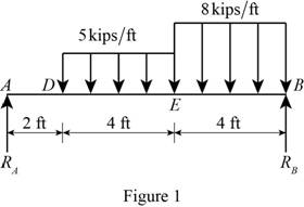
Determine the reaction of the support by taking moment at point B.
Determine the reaction of the support by considering the vertical equilibrium condition:
Substitute
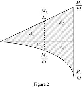
Show the moment
Calculate the moment
Substitute
Calculate the ratio of
Substitute
Calculate the area
Here, b is the width of the triangle in area
Substitute
Calculate the moment
Substitute
Calculate the ratio of
Substitute
Calculate the area
Here,
Substitute
Calculate the moment
Calculate the ratio of
Substitute
Calculate the area
Here,
Substitute
Calculate the moment
Calculate the ratio of
Substitute
Calculate the area
Here,
Substitute
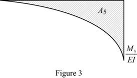
Show the moment
Calculate the moment
Calculate the ratio of
Substitute
Calculate the area
Here,
Substitute
Calculate the slope at the end A related to the point B
Substitute
Calculate the slope
Substitute
Calculate the slope
Substitute
Calculate the slope
Substitute
Let point K be location of the largest downward deflection.
Hence, the slope at point E is greater than zero, the point K of zeros slope lies to the left of the point E.
Calculate the moment
Calculate the ratio of
Substitute
Calculate the moment
Calculate the ratio of
Substitute
Show the moment
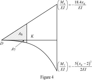
Calculate the area
Substitute
Calculate the area
Substitute
Calculate the slope
Substitute
Differentiate the Equation (1).
Solve the value
Iteration 1:
Substitute 5 for
Substitute 5 for
Iteration 2:
Calculate the value
Substitute 5 for
Similarly calculate the value
| f | ||
| 5 | -10.634 | 69.5 |
| 5.153 | -0.037 | 69.962 |
| 5.0005 | -10.597 | 69.5.02 |
| 5.1525 | 0.001 |
The value of
Calculate the slope at the end A related to the point K
Substitute
Calculate the magnitude
Substitute
Thus, the magnitude
Want to see more full solutions like this?
Chapter 9 Solutions
Mechanics of Materials, CE3110


- Determine the slope and deflection at D for the beam and loading shown in Fig, knowing that the flexural rigidity of the beam isEI= 100 MN-m2.arrow_forwardFor the cantilever beam and loading shown, determine the slope and deflection at end A. Use E= 29 *106 psiarrow_forwardFor the cantilever beam and loading shown, determine the slope and deflection at the free endarrow_forward
- For the simply supported beam carrying the concentrated load P = 276 N at its midspan, determine the magnitude of the maximum slope angle of the beam (in degrees) if d = 2.16 m, E = 12.77 GPa , and I =1681393mm4. NOTE: PLEASE ANSWER IT CORRECTLY. IF YOU ARE NOT SURE ABOUT THE ANSWER, PLEASE SKIP THE QUESTIONPLEASE BOX THE FINAL ANSWER(S)THANK YOU!arrow_forwardFor the cantilever beam and loading shown, determine (a) the slope at point A, (b) the defiection at point A. Use E = 200 GPa. 5kN AThms L W50 x 223 1m 25m—| Fig. P9.104arrow_forwardA simply-supported beam, 9 m in length, is subjected to a uniform load of 20 kN/m applied at the beam's middle third. Determine the maximum deflection. Answer: _____/EIarrow_forward
- For the cantilever beam and loading shown, determine the slope and deflection at end B. Use E= 29 *106 psiarrow_forwardDetermine the maximum deflection of the beam and the slope at ?. Consider ?? constantarrow_forwardA cantilever beam of length 6 m carries a uniformly distributed load of 2.5 kN/m over its entire length. Determine the maximum deflection and slope if E = 210 GPa and I = 12.5 x 106 mm4.arrow_forward
- Determine the value of the slope and deflection of the beam at points B and C. E and I are constant over the beam length. (Set a = 4m, w = 5kN/m, E = 200 GPa, I = 114 x 106 mm4)arrow_forwardDetermine the slope and deflection at the free-end of a cantilever beam using different method. Use virtual work method and Castigliano theorem in solving this problem. Ex. slope- virtual work and deflection - Castigliano theorem; vice-versa. Set P = 75 kN and w = 28 kN/m.arrow_forwardconsider the cantilevered W14 x 30 beam shown E = 29(103) ksi, I = 291 in4 determine the expression for the elastic curve using the coordinate x for 0 < x < 9 ft, where x is in feet. v in ft answer in terms of x determine the maximum slope of the beam, measured counterclockwise from the positive x axis. Theta max in rad. determine the maximum deflection of the beam. Vmax in ft.arrow_forward
 Elements Of ElectromagneticsMechanical EngineeringISBN:9780190698614Author:Sadiku, Matthew N. O.Publisher:Oxford University Press
 Mechanics of Materials (10th Edition)Mechanical EngineeringISBN:9780134319650Author:Russell C. HibbelerPublisher:PEARSON
 Thermodynamics: An Engineering ApproachMechanical EngineeringISBN:9781259822674Author:Yunus A. Cengel Dr., Michael A. BolesPublisher:McGraw-Hill Education
 Control Systems EngineeringMechanical EngineeringISBN:9781118170519Author:Norman S. NisePublisher:WILEY
 Mechanics of Materials (MindTap Course List)Mechanical EngineeringISBN:9781337093347Author:Barry J. Goodno, James M. GerePublisher:Cengage Learning
 Engineering Mechanics: StaticsMechanical EngineeringISBN:9781118807330Author:James L. Meriam, L. G. Kraige, J. N. BoltonPublisher:WILEY