
Concept explainers
Videos
Two cover plates are welded to the rolled-steel beam as shown. Using E = 200 GPa, determine (a) the slope at end A, (b) the deflection at end A. 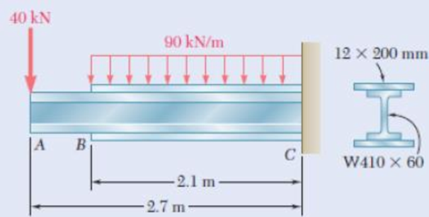
Fig. P9.107
(a)
Find the slope
Answer to Problem 107P
The slope
Explanation of Solution
Given information:
The elastic modulus (E) is
The section of the beam is
The dimension of the top plate and bottom plate is
Calculation:
Refer Appendix C, “Properties of Rolled steel shapes”.
The moment of inertia (I) for the given section is
The depth of the section (D) is
The width of the section (b) is
Use moment area method:
Consider from bottom.
Calculate the neutral axis
Substitute
Top plate:
Calculate the area of the top plate
Since the dimension of the top plate is
Calculate the depth of neutral axis (d) using the formula:
Substitute
Calculate the product of
Substitute
Calculate the moment of inertia (I) using the formula:
Here, b is the width the top plate and h is the height of the top plate.
Substitute 200 mm for b and 12 mm for h.
Bottom plate:
Top plate:
Calculate the area of the bottom plate
Since the dimension of the bottom plate is
Calculate the depth of neutral axis (d) using the formula:
Substitute
Calculate the product of
Substitute
Calculate the moment of inertia (I) using the formula:
Here, b is the width the top plate and h is the height of the top plate.
Substitute
Tabulate the calculated values and compute the moment of inertia (I) as in Table 1.
| Segments | Area, A | Depth, d (mm) | ||
| Top plate | 2400 | 209 | 28,800 | |
| Bottom plate | 2400 | 209 | 28,000 | |
| Summation |
Take the greater value of moment of inertia from the three segments is
Calculate the moment of inertia (I) using the relation:
Substitute
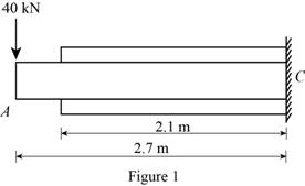
Show the free body diagram of beam by considering the point load as in Figure 1.
Draw the moment diagram of the above beam as in Figure 2.
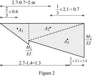
Calculate the moment
Calculate the ratio of
Substitute
Calculate the area
Here,
Substitute 0.6 mm for
Calculate the moment
Calculate the ratio of
Substitute
Calculate the area
Here,
Substitute 2.1 m for
Calculate the area
Substitute
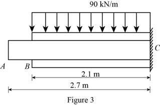
Show the free body diagram of beam by considering the uniformly distributed load as in Figure 3.
Draw the moment diagram of the above beam as in Figure 4.
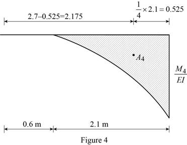
Calculate the moment
Calculate the ratio of
Substitute
Calculate the area
Here,
Substitute
Show the tangent slope and deflection at point A related to reference tangent as in Figure 5.
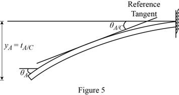
Since the support C has fixed support, the slope
Calculate the slope at the end A related to the fixed end C
Substitute
Calculate the slope at the point A
Substitute 0 for
Thus, the slope
(b)
Find the deflection
Answer to Problem 107P
The deflection
Explanation of Solution
Given information:
The elastic modulus (E) is
The section of the beam is
The dimension of the top plate and bottom plate is
Calculation:
Calculate the deflection at end A related to the fixed end C
Substitute
Calculate the deflection at the point A
Substitute 0 for
Thus, the deflection
Want to see more full solutions like this?
Chapter 9 Solutions
Mechanics of Materials, CE3110


- Determine the slope and deflection at D for the beam and loading shown in Fig, knowing that the flexural rigidity of the beam isEI= 100 MN-m2.arrow_forwardA simply-supported beam, 9 m in length, is subjected to a uniform load of 20 kN/m applied at the beam's middle third. Determine the deflection at x = 7.5. Answer: _____/EIarrow_forwardA 7/8-in.-diameter rod BC is attached to the lever AB and to the fixed support at C. Lever AB has a uniform cross section 38 in. thick and 1 in. deep. For the loading shown, determine the deflection of point A. Use E=29 *106 psi and G=11.2 *106 psi.arrow_forward
- consider the cantilevered W14 x 30 beam shown E = 29(103) ksi, I = 291 in4 determine the maximum slope of the beam, measured counterclockwise from the positive x axis. determine the maximum deflection of the beam. determine the expression for the elastic curve using the coordinate x for 0 < x < 9 ft, where x is in feet.arrow_forwardEach of the links AB and CD is made of aluminum and has a cross-sectional area of 0.2 sq.in. Knowing that they support the rigid member BC, determine the downward deflection (in inches) of point C. if x = 13.7 in, y = 28.1 in, z = 20 in, E = 10754407 psi, and P = 26 kips.arrow_forwardA cantilever beam of length 6 m carries a uniformly distributed load of 2.5 kN/m over its entire length. Determine the maximum deflection and slope if E = 210 GPa and I = 12.5 x 106 mm4.arrow_forward
- For the simply supported beam carrying the concentrated load P = 276 N at its midspan, determine the magnitude of the maximum slope angle of the beam (in degrees) if d = 2.16 m, E = 12.77 GPa , and I =1681393mm4. NOTE: PLEASE ANSWER IT CORRECTLY. IF YOU ARE NOT SURE ABOUT THE ANSWER, PLEASE SKIP THE QUESTIONPLEASE BOX THE FINAL ANSWER(S)THANK YOU!arrow_forwardFor the cantilever beam and loading shown, determine (a) the slope at point A, (b) the defiection at point A. Use E = 200 GPa. 5kN AThms L W50 x 223 1m 25m—| Fig. P9.104arrow_forwardDetermine the value of the slope and deflection of the beam at points B and C. E and I are constant over the beam length. (Set a = 4m, w = 5kN/m, E = 200 GPa, I = 114 x 106 mm4)arrow_forward
- Determine the shape of a fully stressed, simply supported beam that supportsa concentrated force at its center, Fig. 11–11a. The beam has a rectangularcross section of constant width b, and the allowable stress is sallow.arrow_forwardFor the cantilever beam and loading shown, determine the slope and deflection at end A. Use E= 29 *106 psiarrow_forwardDetermine the maximum deflection of the beam and the slope at ?. Consider ?? constantarrow_forward
 Elements Of ElectromagneticsMechanical EngineeringISBN:9780190698614Author:Sadiku, Matthew N. O.Publisher:Oxford University Press
 Mechanics of Materials (10th Edition)Mechanical EngineeringISBN:9780134319650Author:Russell C. HibbelerPublisher:PEARSON
 Thermodynamics: An Engineering ApproachMechanical EngineeringISBN:9781259822674Author:Yunus A. Cengel Dr., Michael A. BolesPublisher:McGraw-Hill Education
 Control Systems EngineeringMechanical EngineeringISBN:9781118170519Author:Norman S. NisePublisher:WILEY
 Mechanics of Materials (MindTap Course List)Mechanical EngineeringISBN:9781337093347Author:Barry J. Goodno, James M. GerePublisher:Cengage Learning
 Engineering Mechanics: StaticsMechanical EngineeringISBN:9781118807330Author:James L. Meriam, L. G. Kraige, J. N. BoltonPublisher:WILEY