Determine the new per unit value of the generator impedance base from the given bases. Generator G: 15 MVA, 13.8 kV, X = 0.15 p.u. Motor M1: 5 MVA, 13.8 kV, X = 0.15 p.u. Motor M2: 5 MVA, 14.4 kV, X = 0.15 p.u. T;: 25 MVA, 13.2 – 161 kV, X = 0.1 p.u. T;:15 MVA, 13.8 –. 161 kV, X = 0.1 p.u. Line: j100 N (actual) Select a base of 100 MVA and 161 kV in the transmission line. T T2 Line pu 1.09 pu 0.15 pu 0.91 pu
Determine the new per unit value of the generator impedance base from the given bases. Generator G: 15 MVA, 13.8 kV, X = 0.15 p.u. Motor M1: 5 MVA, 13.8 kV, X = 0.15 p.u. Motor M2: 5 MVA, 14.4 kV, X = 0.15 p.u. T;: 25 MVA, 13.2 – 161 kV, X = 0.1 p.u. T;:15 MVA, 13.8 –. 161 kV, X = 0.1 p.u. Line: j100 N (actual) Select a base of 100 MVA and 161 kV in the transmission line. T T2 Line pu 1.09 pu 0.15 pu 0.91 pu

Power System Analysis and Design (MindTap Course List)
6th Edition
ISBN:9781305632134
Author:J. Duncan Glover, Thomas Overbye, Mulukutla S. Sarma
Publisher:J. Duncan Glover, Thomas Overbye, Mulukutla S. Sarma
Chapter9: Unsymmetrical Faults
Section: Chapter Questions
Problem 9.5P

Related questions
Question
100%
asap please
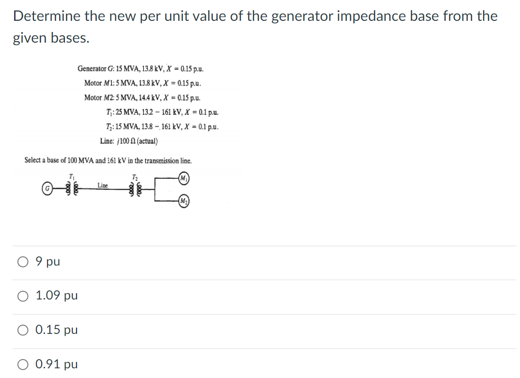
Transcribed Image Text:Determine the new per unit value of the generator impedance base from the
given bases.
Generator G: 15 MVA, 13.8 kV, X = 0.15 p.u.
Motor M1: 5 MVA, 13.8 kV, X = 0.15 p.u.
Motor M2: 5 MVA, 14.4 kV, X = 0.15 p.u.
T;: 25 MVA, 13.2 – 161 kV, X = 0.1 p.u.
T;:15 MVA, 13.8 –. 161 kV, X = 0.1 p.u.
Line: j100 N (actual)
Select a base of 100 MVA and 161 kV in the transmission line.
T
T2
Line
pu
1.09 pu
0.15 pu
0.91 pu
Expert Solution
This question has been solved!
Explore an expertly crafted, step-by-step solution for a thorough understanding of key concepts.

Step by step
Solved in 2 steps with 1 images

Knowledge Booster


Learn more about
Need a deep-dive on the concept behind this application? Look no further. Learn more about this topic, electrical-engineering and related others by exploring similar questions and additional content below.Recommended textbooks for you
Power System Analysis and Design (MindTap Course …
Electrical Engineering
ISBN:
9781305632134
Author:
J. Duncan Glover, Thomas Overbye, Mulukutla S. Sarma
Publisher:
Cengage Learning
Power System Analysis and Design (MindTap Course …
Electrical Engineering
ISBN:
9781305632134
Author:
J. Duncan Glover, Thomas Overbye, Mulukutla S. Sarma
Publisher:
Cengage Learning