
Tutorials in Introductory Physics
1st Edition
ISBN: 9780130970695
Author: Peter S. Shaffer, Lillian C. McDermott
Publisher: Addison Wesley
expand_more
expand_more
format_list_bulleted
Concept explainers
Videos
Textbook Question
Chapter 10.2, Problem 4aT
On the diagram at right, draw one ray from the pin that is reflected by the mirror.,br/>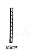
If you were to place your eye so that you were looking back along the reflected ray, what would you see?
From one ray alone do you have enough information to determine the location of the image? If not, what can you infer about the location of the image from only a single ray?
Expert Solution & Answer
Want to see the full answer?
Check out a sample textbook solution
Students have asked these similar questions
The diagram at the right shows light refracting from material A into material B. The index of refraction of material A is 2.24. Use your protractor to measure angles and determine the index of refraction of material B. (HINT: The angle measures are multiples of 15 degrees.)
Two plane mirrors are at an angle of ?1 = 57.6° with each other as in the side view shown in the figure below. If a horizontal ray is incident on mirror 1, at what angle ?2 does the outgoing reflected ray make with the surface of mirror 2?
in step 1 why is the image distance -4 cm?
Chapter 10 Solutions
Tutorials in Introductory Physics
Ch. 10.1 - Prob. 1aTCh. 10.1 - Predict how each of the following changes would...Ch. 10.1 - A mask with a circular hole is placed between a...Ch. 10.1 - What do your observations suggest about the path...Ch. 10.1 - Imagine that you held a string of closely spaced...Ch. 10.1 - The mask used in parts C-E is replaced by one that...Ch. 10.1 - Prob. 1gTCh. 10.1 - Predict what you would see on the screen when an...Ch. 10.1 - Predict the size of the lit region on the screen...Ch. 10.1 - Suppose that the bulb were replaced by a long...
Ch. 10.1 - Prob. 2cTCh. 10.1 - Predict what you would see on the screen at the...Ch. 10.1 - Suppose that the light from the top bulb in the...Ch. 10.1 - Predict what you would see on the screen in the...Ch. 10.2 - Close one eye and lean down so that your open eye...Ch. 10.2 - Suppose that you placed your finger behind the...Ch. 10.2 - Prob. 1cTCh. 10.2 - Prob. 1dTCh. 10.2 - Place your head so that you can see the image of...Ch. 10.2 - Move the nail off w the right side of the mirror...Ch. 10.2 - Prob. 3aTCh. 10.2 - Turn the large sheet of paper over (or obtain a...Ch. 10.2 - Remove the mirror and the object nail. For each...Ch. 10.2 - On the diagram at right, draw one ray from the pin...Ch. 10.2 - Prob. 4bTCh. 10.2 - Determine the image location using the method of...Ch. 10.3 - A pin is placed In front of a cylindrical mirror...Ch. 10.3 - Could you use any two rays (even those that do not...Ch. 10.3 - Observers at M and N arc looking at an image of...Ch. 10.3 - Stick a pin into a piece of cardboard and place...Ch. 10.3 - Gradually decrease the angle between the mirrors...Ch. 10.4 - Prob. 1bTCh. 10.4 - Three students are discussing their results from...Ch. 10.4 - For each case shown below, determine and label the...Ch. 10.4 - In each of the previous cases, predict what would...Ch. 10.4 - Prob. 2cTCh. 10.4 - Explain how you can use a screen to determine the...Ch. 10.5 - Look at very distant object through a convex lens....Ch. 10.5 - Consider a point on the distant object that is...Ch. 10.5 - Suppose that you placed a very small bulb at the...Ch. 10.5 - Consider the ray chai is parallel to the principal...Ch. 10.5 - Consider the ray that goes through the focal point...Ch. 10.5 - How can you use these two rays to determine the...Ch. 10.5 - Consider the ray from the easer that strikes the...Ch. 10.5 - Draw the continuation of the two remaining rays...Ch. 10.5 - Prob. 2fTCh. 10.5 - The diagram below shows a small object placed near...Ch. 10.5 - A lens, a bulb, and a screen are arranged as shown...Ch. 10.5 - Obtain the necessary equipment and check your...Ch. 10.5 - Prob. 3cTCh. 10.6 - The diagram at right illustrates what an observer...Ch. 10.6 - Obtain two soda cans and a cardboard tube that has...Ch. 10.6 - Could an observer at each of the labeled points...Ch. 10.6 - Use the above diagram to answer the following...Ch. 10.6 - Obtain convex lens. Use the lens as a magnifying...Ch. 10.6 - Draw a ray diagram that shows how to determine the...Ch. 10.6 - The lateral magnification, m1 , is defined as...Ch. 10.6 - The angular magnification, m , is defined as m= ,...
Additional Science Textbook Solutions
Find more solutions based on key concepts
3. What is free-fall, and why does it make you weightless? Briefly describe why astronauts are weightless in th...
The Cosmic Perspective
Invent and describe an experiment to estimate the speed of sound in air. You can use only everyday items.
College Physics
Two identical bubbles of gas form at the bottom of a lake, then rise to the surface. Because the pressure is mu...
An Introduction to Thermal Physics
Are the seasons (summer or winter) the same in the Northern and Southern Hemispheres at the same time? When it ...
Lecture- Tutorials for Introductory Astronomy
Discuss whether Gauss's law can be applied to other forces, and if so, which ones.
University Physics Volume 2
12. Light of wavelength λ and frequency f passes through a single slit of width a. The diffraction pattern is o...
College Physics (10th Edition)
Knowledge Booster


Learn more about
Need a deep-dive on the concept behind this application? Look no further. Learn more about this topic, physics and related others by exploring similar questions and additional content below.Similar questions
- An object is placed 10 m before a convex lens with focal length 5.2 m . Another concave lens is placed 15.6 m behind the first lens with a focal length −7.2 m (see the figure below). Note: Make a ray diagram sketch in order to check your numerical answer. At what distance is the first image from the first lens? Answer in units of m. What is the magnification of the first image? At what distance is the second image from the second lens? Answer in units of m. What is the magnification of the final image, when compared to the initial object?arrow_forwardConsider a light ray from a fish that emerges into the air with angle α as shown on the left. Now consider this same light ray originating from the fish going through glass before emerging into the air at angle β, as shown on the right. Which angle is larger: α or β? (Note: the path shown through the glass is illustrative only – you might have to change the slope.arrow_forwardThe ray diagrams shown trace the path that light takes in order to locate the image formed by a concave mirror. Points C and f indicate the mirror's center center of curvature and focal point. Which ray diagrams are drawn incorrectly.arrow_forward
- A 1.5 cmcm high object is located 30 cmcm from a diverging lens, whose focal length is 11 cmcm . What is the height of the image produced by the lens? You have determined the height of the image using numerical methods and, in so doing, have also determined its position, s′s′s'. Now, use graphical methods to evaluate your results.The diagram below shows the object, a ray (ray 1) parallel to the optic axis of the lens, and a ray (ray 2) proceeding toward the first focal point of the lens. Draw the refracted rays and the image produced by the lens. Make sure you extend the refracted rays sufficiently backward in order to find the image. Keep in mind that principal-ray diagrams must be drawn accurately to give good results!arrow_forwardThank you so much in advance. The diagram shows a lens with a positive focal length 11 cm. (a) If we place an object at a distance of 25 cm from the lens, where will the resulting image position on the other side of the lens be found? Include units in answer, (b) With the object at 25 cm from the lens, what will the magnification be for the image at this position? (c) If we place an object at a distance of 4 cm from the lens, where will the resulting image position be found? (d) With the object at 4 cm from the lens, what will the magnification be for the image at this position?arrow_forwardAfter reflecting, at what incident angle in the 1st mirror would this ray hit the middle of the 2nd mirror? Illustrate the light ray's path. * Arrow represents the light ray. *arrow_forward
- Four ray diagrams are shown below. f1, f2 are the focal points for the lenses respectively as shown from left to right. when both focal points occur at the same point their position is designated as "f1/f2". Identify the TWO ray diagrams that show the correct position for the FINAL image for the two-lens systems shown below.arrow_forwardConsider the compound optical system shown in the diagram, where two thin lenses of focal lengths 7.5 cm (left lens) and 35 cm (right lens) are separated by a distance 25 cm. If a 2.9 cm tall object is placed as indicated in part (a), and the image formed is 0.74 cm tall, what is the magnification of the first lens? M1 = b. Using the information from part (a), calculate the image distance, in centimeters, from the first lens. di1 =arrow_forwardDraw a ray diagram for each of the following, and then draw the image formed. Please provide complete labels in the diagrams, as well as the size, orientation, type, and position of the image. Thank you so much! You may only opt to answer number 2 if answering all is not allowed:) 1. Object location at 2F’ 2. Object location at F’ 3. Object location beyond 2F’arrow_forward
- in the image is my assignment. I just want to know if the boxed answer is correct, for problem 1, and whether or not the bolded answers for questions 2 and 3 are correct.arrow_forwardDraw a ray diagram for each of the following, and then draw the image formed. Please provide complete labels in the diagrams, as well as the size, orientation, type, and position of the image. You can also opt to only answer number 3 if all is not allowed. Thank you so much! 1. Object location at 2F’ 2. Object location at F’ 3. Object location beyond 2F’arrow_forwardA concave lens refracts parallel rays in such a way that they are bent away from the axis of the lens. For this reason, a concave lens is referred to as a diverging lens. Part A: Consider the following diagrams, where F represents the focal point of a concave lens. In these diagrams, the image formed by the lens is obtained using the ray tracing technique. Which diagrams are accurate?(Figure 1) *Type A if you think that only diagram A is correct, type AB if you think that only diagrams A and B are correct, and so on. Part B: If the focal length of the concave lens is -7.50 cm , at what distance d_o from the lens should an object be placed so that its image is formed 3.70 cm from the lens?arrow_forward
arrow_back_ios
SEE MORE QUESTIONS
arrow_forward_ios
Recommended textbooks for you
 Glencoe Physics: Principles and Problems, Student...PhysicsISBN:9780078807213Author:Paul W. ZitzewitzPublisher:Glencoe/McGraw-Hill
Glencoe Physics: Principles and Problems, Student...
Physics
ISBN:9780078807213
Author:Paul W. Zitzewitz
Publisher:Glencoe/McGraw-Hill
AP Physics 2 - Geometric Optics: Mirrors and Lenses - Intro Lesson; Author: N. German;https://www.youtube.com/watch?v=unT297HdZC0;License: Standard YouTube License, CC-BY