
Tutorials in Introductory Physics
1st Edition
ISBN: 9780130970695
Author: Peter S. Shaffer, Lillian C. McDermott
Publisher: Addison Wesley
expand_more
expand_more
format_list_bulleted
Concept explainers
Videos
Textbook Question
Chapter 10.5, Problem 1cT
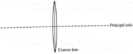
Suppose that you placed a very small bulb at the location of the image in part B.
How would the rays from the bulb that have passed through the lens be oriented? Draw a diagram to illustrate your answer. Explain.
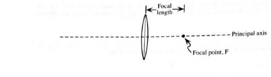
The point of intersection of the principle axis and the image of a very distant object is called the focal point. The distance between the center of the lens and the focal point is called the focal length.
Expert Solution & Answer
Want to see the full answer?
Check out a sample textbook solution
Students have asked these similar questions
Thank you so much in advance.
The diagram shows a lens with a positive focal length 11 cm. (a) If we place an object at a distance of 25 cm from the lens, where will the resulting image position on the other side of the lens be found? Include units in answer, (b) With the object at 25 cm from the lens, what will the magnification be for the image at this position? (c) If we place an object at a distance of 4 cm from the lens, where will the resulting image position be found? (d) With the object at 4 cm from the lens, what will the magnification be for the image at this position?
Sketched below are several objects (the arrows labeled "O") in front of lenses. In each case, carefully redraw the sketch on your whiteboard, and then(a) Draw 3 principal rays leaving the top of the object;(b) Locate the image;(c) State whether the image is real or virtual, inverted or upright, and larger or smaller than the object.
(iv) For diagram #iii, suppose the focal length is 5 cm and the object is placed 7 cm from the lens. Find the exact location and magnification of the image. Does this agree with your expectation from the ray diagram?
Place your object at a distance equal to the focal length (f) of your mirror. Where is your image located? Describe the type of image formed based on size, orientation, and condition, and provide screenshots of your set-up.
Chapter 10 Solutions
Tutorials in Introductory Physics
Ch. 10.1 - Prob. 1aTCh. 10.1 - Predict how each of the following changes would...Ch. 10.1 - A mask with a circular hole is placed between a...Ch. 10.1 - What do your observations suggest about the path...Ch. 10.1 - Imagine that you held a string of closely spaced...Ch. 10.1 - The mask used in parts C-E is replaced by one that...Ch. 10.1 - Prob. 1gTCh. 10.1 - Predict what you would see on the screen when an...Ch. 10.1 - Predict the size of the lit region on the screen...Ch. 10.1 - Suppose that the bulb were replaced by a long...
Ch. 10.1 - Prob. 2cTCh. 10.1 - Predict what you would see on the screen at the...Ch. 10.1 - Suppose that the light from the top bulb in the...Ch. 10.1 - Predict what you would see on the screen in the...Ch. 10.2 - Close one eye and lean down so that your open eye...Ch. 10.2 - Suppose that you placed your finger behind the...Ch. 10.2 - Prob. 1cTCh. 10.2 - Prob. 1dTCh. 10.2 - Place your head so that you can see the image of...Ch. 10.2 - Move the nail off w the right side of the mirror...Ch. 10.2 - Prob. 3aTCh. 10.2 - Turn the large sheet of paper over (or obtain a...Ch. 10.2 - Remove the mirror and the object nail. For each...Ch. 10.2 - On the diagram at right, draw one ray from the pin...Ch. 10.2 - Prob. 4bTCh. 10.2 - Determine the image location using the method of...Ch. 10.3 - A pin is placed In front of a cylindrical mirror...Ch. 10.3 - Could you use any two rays (even those that do not...Ch. 10.3 - Observers at M and N arc looking at an image of...Ch. 10.3 - Stick a pin into a piece of cardboard and place...Ch. 10.3 - Gradually decrease the angle between the mirrors...Ch. 10.4 - Prob. 1bTCh. 10.4 - Three students are discussing their results from...Ch. 10.4 - For each case shown below, determine and label the...Ch. 10.4 - In each of the previous cases, predict what would...Ch. 10.4 - Prob. 2cTCh. 10.4 - Explain how you can use a screen to determine the...Ch. 10.5 - Look at very distant object through a convex lens....Ch. 10.5 - Consider a point on the distant object that is...Ch. 10.5 - Suppose that you placed a very small bulb at the...Ch. 10.5 - Consider the ray chai is parallel to the principal...Ch. 10.5 - Consider the ray that goes through the focal point...Ch. 10.5 - How can you use these two rays to determine the...Ch. 10.5 - Consider the ray from the easer that strikes the...Ch. 10.5 - Draw the continuation of the two remaining rays...Ch. 10.5 - Prob. 2fTCh. 10.5 - The diagram below shows a small object placed near...Ch. 10.5 - A lens, a bulb, and a screen are arranged as shown...Ch. 10.5 - Obtain the necessary equipment and check your...Ch. 10.5 - Prob. 3cTCh. 10.6 - The diagram at right illustrates what an observer...Ch. 10.6 - Obtain two soda cans and a cardboard tube that has...Ch. 10.6 - Could an observer at each of the labeled points...Ch. 10.6 - Use the above diagram to answer the following...Ch. 10.6 - Obtain convex lens. Use the lens as a magnifying...Ch. 10.6 - Draw a ray diagram that shows how to determine the...Ch. 10.6 - The lateral magnification, m1 , is defined as...Ch. 10.6 - The angular magnification, m , is defined as m= ,...
Additional Science Textbook Solutions
Find more solutions based on key concepts
Explain all answers clearly, with complete sentences and proper essay structure if needed. An asterisk (*) desi...
Cosmic Perspective Fundamentals
The distance of first baseman for the second baseman.
Physics (5th Edition)
16. On the Apollo 14 mission to the moon, astronaut Alan Shepard hit a golf ball with a 6 iron. The free-fall a...
Physics for Scientists and Engineers: A Strategic Approach, Vol. 1 (Chs 1-21) (4th Edition)
The diagram shows Bob’s view of the passing of two identical spaceships. Anna’s and his own, where v=2 . The le...
Modern Physics
Knowledge Booster


Learn more about
Need a deep-dive on the concept behind this application? Look no further. Learn more about this topic, physics and related others by exploring similar questions and additional content below.Similar questions
- Four ray diagrams are shown below. f1, f2 are the focal points for the lenses respectively as shown from left to right. when both focal points occur at the same point their position is designated as "f1/f2". Identify the TWO ray diagrams that show the correct position for the FINAL image for the two-lens systems shown below.arrow_forwardThe ray diagrams shown trace the path that light takes in order to locate the image formed by a concave mirror. Points C and f indicate the mirror's center center of curvature and focal point. Which ray diagrams are drawn incorrectly.arrow_forwardDraw a ray diagram for each of the following, and then draw the image formed. Please provide complete labels in the diagrams, as well as the size, orientation, type, and position of the image. Thank you so much! You may only opt to answer number 2 if answering all is not allowed:) 1. Object location at 2F’ 2. Object location at F’ 3. Object location beyond 2F’arrow_forward
- Construct ray diagrams to determine the location, orientation, size, and type of images formed by a curved mirror. Using the protractor and the ruler, copy each of the diagrams (A – F) below on a separate sheet of paper. As much as possible, use the four principal rays to locate the image formed in a curved mirror.arrow_forwardfor part 2 the options are Where will the image of this lens form closest to? (A or B or C or D or E or F or G or H) The image formed by this lens is a (real or virtual) (inverted or upright)arrow_forwardThe diagram at the right shows light refracting from material A into material B. The index of refraction of material A is 2.24. Use your protractor to measure angles and determine the index of refraction of material B. (HINT: The angle measures are multiples of 15 degrees.)arrow_forward
- Draw a ray diagram for each of the following, and then draw the image formed. Please provide complete labels in the diagrams, as well as the size, orientation, type, and position of the image. You can also opt to only answer number 3 if all is not allowed. Thank you so much! 1. Object location at 2F’ 2. Object location at F’ 3. Object location beyond 2F’arrow_forwardDraw a ray diagram for each of the following, and then draw the image formed. Please provide complete labels in the diagrams, as well as the size, orientation, type, and position of the image. Thank you so much! 1. Object location at 2F’ 2. Object location at F’ 3. Object location beyond 2F’arrow_forwarddescribe how a ray diagram can be used to show the location of an image formed by a concave mirror. Describe the rays that can be used, where they travel before and after striking the mirror, and where the images form.arrow_forward
- An object is placed 10 m before a convex lens with focal length 5.2 m . Another concave lens is placed 15.6 m behind the first lens with a focal length −7.2 m (see the figure below). Note: Make a ray diagram sketch in order to check your numerical answer. At what distance is the first image from the first lens? Answer in units of m. What is the magnification of the first image? At what distance is the second image from the second lens? Answer in units of m. What is the magnification of the final image, when compared to the initial object?arrow_forwardA 1.5 cmcm high object is located 30 cmcm from a diverging lens, whose focal length is 11 cmcm . What is the height of the image produced by the lens? You have determined the height of the image using numerical methods and, in so doing, have also determined its position, s′s′s'. Now, use graphical methods to evaluate your results.The diagram below shows the object, a ray (ray 1) parallel to the optic axis of the lens, and a ray (ray 2) proceeding toward the first focal point of the lens. Draw the refracted rays and the image produced by the lens. Make sure you extend the refracted rays sufficiently backward in order to find the image. Keep in mind that principal-ray diagrams must be drawn accurately to give good results!arrow_forwardAnalyse the following observation table showing variation of image distance with object distance in case of a convex lens and answer the question that follow without doing any calculations1) What is the focal length of the convex lens? Give reason in support of your answer2) Write the serial number of that observation which is not correct. How did you arrive at this conclusion.3) Take an appropriate scale to draw ray diagram for the observation at S. No. 4 and find the approximate value of the magnification.Class - 10thChapter - Light, reflection and refraction.arrow_forward
arrow_back_ios
SEE MORE QUESTIONS
arrow_forward_ios
Recommended textbooks for you
 University Physics Volume 3PhysicsISBN:9781938168185Author:William Moebs, Jeff SannyPublisher:OpenStax
 Glencoe Physics: Principles and Problems, Student...PhysicsISBN:9780078807213Author:Paul W. ZitzewitzPublisher:Glencoe/McGraw-Hill
University Physics Volume 3
Physics
ISBN:9781938168185
Author:William Moebs, Jeff Sanny
Publisher:OpenStax
Glencoe Physics: Principles and Problems, Student...
Physics
ISBN:9780078807213
Author:Paul W. Zitzewitz
Publisher:Glencoe/McGraw-Hill
AP Physics 2 - Geometric Optics: Mirrors and Lenses - Intro Lesson; Author: N. German;https://www.youtube.com/watch?v=unT297HdZC0;License: Standard YouTube License, CC-BY