
Mechanics of Materials, 7th Edition
7th Edition
ISBN: 9780073398235
Author: Ferdinand P. Beer, E. Russell Johnston Jr., John T. DeWolf, David F. Mazurek
Publisher: McGraw-Hill Education
expand_more
expand_more
format_list_bulleted
Videos
Textbook Question
Chapter 11.5, Problem 65P
Using the method of work and energy, determine the slope at point D caused by the couple M0.
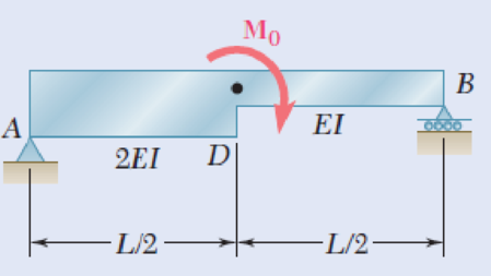
Fig. P11.65
Expert Solution & Answer
Want to see the full answer?
Check out a sample textbook solution
Students have asked these similar questions
7
The coefficient of restitution (e) describes the extent to which the deformation during impact is elastic (e = 1) vs. plastic (e = 0).
True
False
Determine the sag of a 30-ft chain that is attached to two points at the same elevation that are 20 ft apart.
Which of the following gives the closest value of the coefficient of restitution, e, between the block and the slender rod?
0.929
0.607
0.671
0.252
Chapter 11 Solutions
Mechanics of Materials, 7th Edition
Ch. 11.3 - Determine the modulus of resilience for each of...Ch. 11.3 - Determine the modulus of resilience for each of...Ch. 11.3 - Determine the modulus of resilience for each of...Ch. 11.3 - Determine the modulus of resilience for each of...Ch. 11.3 - The stress-strain diagram shown has been drawn...Ch. 11.3 - The stress-strain diagram shown has been drawn...Ch. 11.3 - Prob. 7PCh. 11.3 - Prob. 8PCh. 11.3 - Using E = 29 106 psi, determine (a) the strain...Ch. 11.3 - Using E = 200 GPa, determine (a) the strain energy...
Ch. 11.3 - A 30-in. length of aluminum pipe of...Ch. 11.3 - A single 6-mm-diameter steel pin B is used to...Ch. 11.3 - Prob. 13PCh. 11.3 - Prob. 14PCh. 11.3 - The assembly ABC is made of a steel for which E =...Ch. 11.3 - Show by integration that the strain energy of the...Ch. 11.3 - Prob. 17PCh. 11.3 - Prob. 18PCh. 11.3 - Prob. 19PCh. 11.3 - 11.18 through 11.21 In the truss shown, all...Ch. 11.3 - Prob. 21PCh. 11.3 - Each member of the truss shown is made of aluminum...Ch. 11.3 - Each member of the truss shown is made of aluminum...Ch. 11.3 - 11.24 through 11.27 Taking into account only the...Ch. 11.3 - Prob. 25PCh. 11.3 - 11.24 through 11.27 Taking into account only the...Ch. 11.3 - 11.24 through 11.27 Taking into account only the...Ch. 11.3 - Prob. 28PCh. 11.3 - Prob. 29PCh. 11.3 - Prob. 30PCh. 11.3 - 11.30 and 11.31 Using E = 200 GPa, determine the...Ch. 11.3 - Assuming that the prismatic beam AB has a...Ch. 11.3 - Prob. 33PCh. 11.3 - The design specifications for the steel shaft AB...Ch. 11.3 - Show by integration that the strain energy in the...Ch. 11.3 - The state of stress shown occurs in a machine...Ch. 11.3 - Prob. 37PCh. 11.3 - The state of stress shown occurs in a machine...Ch. 11.3 - Prob. 39PCh. 11.3 - Prob. 40PCh. 11.3 - Prob. 41PCh. 11.5 - A 5-kg collar D moves along the uniform rod AB and...Ch. 11.5 - The 18-lb cylindrical block E has a horizontal...Ch. 11.5 - The cylindrical block E has a speed v0 =16 ft/s...Ch. 11.5 - Prob. 45PCh. 11.5 - Prob. 46PCh. 11.5 - The 48-kg collar G is released from rest in the...Ch. 11.5 - Prob. 48PCh. 11.5 - Prob. 49PCh. 11.5 - Prob. 50PCh. 11.5 - Prob. 51PCh. 11.5 - The 2-kg block D is dropped from the position...Ch. 11.5 - The 10-kg block D is dropped from a height h = 450...Ch. 11.5 - Prob. 54PCh. 11.5 - A 160-lb diver jumps from a height of 20 in. onto...Ch. 11.5 - Prob. 56PCh. 11.5 - A block of weight W is dropped from a height h...Ch. 11.5 - 11.58 and 11.59 Using the method of work and...Ch. 11.5 - 11.58 and 11.59 Using the method of work and...Ch. 11.5 - 11.60 and 11.61 Using the method of work and...Ch. 11.5 - 11.60 and 11.61 Using the method of work and...Ch. 11.5 - 11.62 and 11.63 Using the method of work and...Ch. 11.5 - 11.62 and 11.63 Using the method of work and...Ch. 11.5 - Using the method of work and energy, determine the...Ch. 11.5 - Using the method of work and energy, determine the...Ch. 11.5 - The 20-mm diameter steel rod BC is attached to the...Ch. 11.5 - Torques of the same magnitude T are applied to the...Ch. 11.5 - Prob. 68PCh. 11.5 - The 20-mm-diameter steel rod CD is welded to the...Ch. 11.5 - The thin-walled hollow cylindrical member AB has a...Ch. 11.5 - 11.71 and 11.72 Each member of the truss shown has...Ch. 11.5 - 11.71 and 11.72 Each member of the truss shown has...Ch. 11.5 - Each member of the truss shown is made of steel...Ch. 11.5 - Each member of the truss shown is made of steel....Ch. 11.5 - Each member of the truss shown is made of steel...Ch. 11.5 - The steel rod BC has a 24-mm diameter and the...Ch. 11.9 - 11.77 and 11.78 Using the information in Appendix...Ch. 11.9 - 11.77 and 11.78 Using the information in Appendix...Ch. 11.9 - 11.79 through 11.82 For the beam and loading...Ch. 11.9 - 11.79 through 11.82 For the beam and loading...Ch. 11.9 - 11.79 through 11.82 For the beam and loading...Ch. 11.9 - 11.79 through 11.82 For the beam and loading...Ch. 11.9 - 11.83 through 11.85 For the prismatic beam shown,...Ch. 11.9 - 11.83 through 11.85 For the prismatic beam shown,...Ch. 11.9 - 11.83 through 11.85 For the prismatic beam shown,...Ch. 11.9 - 11.86 through 11.88 For the prismatic beam shown,...Ch. 11.9 - 11.86 through 11.88 For the prismatic beam shown,...Ch. 11.9 - 11.86 through 11.88 For the prismatic beam shown,...Ch. 11.9 - For the prismatic beam shown, determine the slope...Ch. 11.9 - For the prismatic beam shown, determine the slope...Ch. 11.9 - For the beam and loading shown, determine the...Ch. 11.9 - For the beam and loading shown, determine the...Ch. 11.9 - 11.93 and 11.94 For the beam and loading shown,...Ch. 11.9 - 11.93 and 11.94 For the beam and loading shown,...Ch. 11.9 - For the beam and loading shown, determine the...Ch. 11.9 - For the beam and loading shown, determine the...Ch. 11.9 - Prob. 97PCh. 11.9 - For the beam and loading shown, determine the...Ch. 11.9 - 11.99 and 11.100 For the truss and loading shown,...Ch. 11.9 - 11.99 and 11.100 For the truss and loading shown,...Ch. 11.9 - 11.101 and 11.102 Each member of the truss shown...Ch. 11.9 - 11.101 and 11.102 Each member of the truss shown...Ch. 11.9 - 11.103 and 11.104 Each member of the truss shown...Ch. 11.9 - 11.103 and 11 104 Each member of the truss shown...Ch. 11.9 - A uniform rod of flexural rigidity EI is bent and...Ch. 11.9 - For the uniform rod and loading shown and using...Ch. 11.9 - For the beam and loading shown and using...Ch. 11.9 - Two rods AB and BC of the same flexural rigidity...Ch. 11.9 - Three rods, each of the same flexural rigidity EI,...Ch. 11.9 - Three rods, each of the same flexural rigidity EI,...Ch. 11.9 - 11.111 through 11.115 Determine the reaction at...Ch. 11.9 - 11.111 through 11.115 Determine the reaction at...Ch. 11.9 - 11.111 through 11.115 Determine the reaction at...Ch. 11.9 - 11.111 through 11.115 Determine the reaction at...Ch. 11.9 - 11.111 through 11.115 Determine the reaction at...Ch. 11.9 - For the uniform beam and loading shown, determine...Ch. 11.9 - 11.117 through 11.120 Three members of the same...Ch. 11.9 - 11.117 through 11.120 Three members of the same...Ch. 11.9 - 11.117 through 11.120 Three members of the same...Ch. 11.9 - 11.117 through 11.120 Three members of the same...Ch. 11.9 - 11.121 and 11.122 Knowing that the eight members...Ch. 11.9 - 11.121 and 11.122 Knowing that the eight members...Ch. 11 - Rod AB is made of a steel for which the yield...Ch. 11 - Each member of the truss shown is made of steel...Ch. 11 - The ship at A has just started to drill for oil on...Ch. 11 - Collar D is released from rest in the position...Ch. 11 - Each member of the truss shown is made of steel...Ch. 11 - A block of weight W is placed in contact with a...Ch. 11 - Two solid steel shafts are connected by the gears...Ch. 11 - A 160-lb diver jumps from a height of 20 in. onto...Ch. 11 - For the prismatic beam shown, determine the slope...Ch. 11 - A disk of radius a has been welded to end B of the...Ch. 11 - A uniform rod of flexural rigidity EI is bent and...Ch. 11 - The steel bar ABC has a square cross section of...
Knowledge Booster


Learn more about
Need a deep-dive on the concept behind this application? Look no further. Learn more about this topic, mechanical-engineering and related others by exploring similar questions and additional content below.Similar questions
- Two types of motorcycle, Type A has two identical and independent tires, and the failure rate of each tire is 0.0006 failures per hour. Type B has three identical and independent tires, and the failure rate of each tire is 0.0006 failures per hour. Obviously, when any one of the tires for both types is punctured, the motorcycle cannot be driven. Calculate the following for both types A and B: (a) Motorcycle failure rate with respect to tires. (b) Motorcycle reliability for a 20-h mission with respect to tires. (c) Motorcycle mean time to failure with respect to tires. (d) Which motorcycle type would you recommend buying and why?arrow_forward21.50 Derive Eq. (21.14).arrow_forward7. During impact, particles collide with a very short interaction period. The interparticle impulse during an impact collision includes a deformation impulse as particles undergo some combination of elastic and plastic deformation plus a restitution impulse during which some portion of of the deformation is reversed. The magnitude of the restitution impulse is always greater than that of the deformation impulse. True Falsearrow_forward
- 1.A person is to be released from rest on a swing pulled away from the vertical by an angle of 20.0°. The two frayed ropes of the swing are 2.75 m long, and will break if the tension in either of them exceeds 355 N. (a) What is the maximum weight the person can have and not break the ropes? (b)If the person is released at an angle greater than 20.0°, does the maximum weight increase, decrease, or stay the same? (c)Solve in Newton Law, Conversation Law, and Work-Kinetic Theorem.arrow_forward9..111111arrow_forward13. An object (at earth) at rest with a mass of 3kg is being dropped 3m above the spring whose constant is 10N/mm. If the spring has to stopped the falling object, determine the magnitude of deflection of the spring right after the stoppage. Assume no energy loss during operation. Derive with the formula below, show the cancellation, explain the step by step and DRAW a free body diagram/figure. refer with this: PE1 + KE1 + U1 + WF1 + Q1 + W1 = PE2 + KE2 + U2 + WF2 + Q2 + W2 + E losses.arrow_forward
- Determine x(t) when t=0.5 seconds, t=1.0 seconds, t=3 seconds, t=4.5 seconds and t=8 seconds.arrow_forwardA two degrees of freedom mass spring system is fixed at one end, where independent masses can move only in the vertical direction. Considering the system as finite elements, determine the vertical displacement for each mass. Also draw the free body diagram of this system. Use 'X' KN/m as the stiffness value for all the springs and 'Y' Kg as the value for all masses. Where, 'X'= (63) 'Y'= (93)arrow_forwardA rope having a weight per unit length of 0.4 lb/ft is wound 2 1/2 Times around a horizontal rod. Knowing that the coefficient of static friction between the rope and the rod is 0.30, determine the minimum length x of rope that should be left hanging if a 100-lb load is to be supported.arrow_forward
- Required minimum velocity (m/s) of the particle maximum velocity (m/s) if maximum tension does not exceed 141.12 Narrow_forwardTwo loads are supported by cable ABCD, as shown. Determine the value of the load P such that the distance xB is 3 ft. Determine by what percentage this distance increases, if the load P increases by 20%.arrow_forwardTwo types of energy-absorbing fenders designed to be used on a pier are statically loaded. The force-deflection curve for each type of fender is given in the graph. Determine the maximum deflection of each fender when a 90-ton ship moving at 1 mi/h strikes the fender and is brought to rest.arrow_forward
arrow_back_ios
SEE MORE QUESTIONS
arrow_forward_ios
Recommended textbooks for you
 Principles of Heat Transfer (Activate Learning wi...Mechanical EngineeringISBN:9781305387102Author:Kreith, Frank; Manglik, Raj M.Publisher:Cengage Learning
Principles of Heat Transfer (Activate Learning wi...
Mechanical Engineering
ISBN:9781305387102
Author:Kreith, Frank; Manglik, Raj M.
Publisher:Cengage Learning
Mechanical SPRING DESIGN Strategy and Restrictions in Under 15 Minutes!; Author: Less Boring Lectures;https://www.youtube.com/watch?v=dsWQrzfQt3s;License: Standard Youtube License