
Mechanics of Materials, 7th Edition
7th Edition
ISBN: 9780073398235
Author: Ferdinand P. Beer, E. Russell Johnston Jr., John T. DeWolf, David F. Mazurek
Publisher: McGraw-Hill Education
expand_more
expand_more
format_list_bulleted
Videos
Textbook Question
Chapter 11.3, Problem 34P
The design specifications for the steel shaft AB require that the shaft acquire a strain energy of 400 in • lb as the 25-kip • in. torque is applied. Using G = 11.2 × 10⁶ psi, determine (a) the largest inner diameter of the shaft that can be used, (b) the corresponding maximum shearing stress in the shaft.
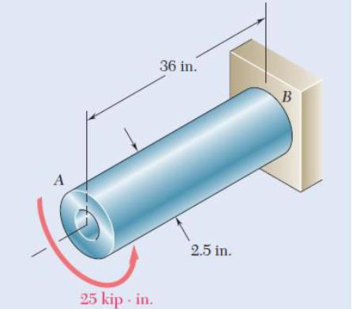
Fig. P11.34
Expert Solution & Answer
Want to see the full answer?
Check out a sample textbook solution
Students have asked these similar questions
PART 1
My answer
Ay=14.38
Cy=13.62
Part 2
Determine the shear force acting at each of the following locations:
(a) x = 4.25- (i.e., just to the left of point B.)
(b) x = 4.25+ (i.e., just to the right of point B.)
(c) x = 9.25-(i.e., just to the left of point C)
(d) x = 9.25+ (i.e., just to the right of point C)
My Answer:
(a) V= 14.38 kN
(b) V= 14.38 kN
(c) V= 14.38 kN
(d) V= 28 kN
Part 3
Determine the bending-moment acting at each of the following locations:
(a) x = 4.25-(i.e.. just to the left of point B.)
(b) x = 4.25+ (i.e.. just to the right of point B.)
(c) x = 9.25 m (i.e., at support C)
(d) x = 8.25 m
My Answer:
(a) M= 61.115kN-m
(b) M= -148.885 kN-m
(c) M= -76.985 kN-m
(d) M= -91.365 kN-m
Part 4:
Use your bending-moment diagram to determine the maximum positive bending moment, Mmax, pos, and the maximum negative bending moment, Mmax, neg. Use the bending-moment sign convention detailed in Section 7.2. The maximum negative bending moment is the negative moment with…
Determine the width and thickness of the leaves (in mm) of a leaf spring using the following specifications:
Total load = 140 kN;
Number of springs supporting the load = 4; Maximum number of leaves = 10;
Span of the spring = 1000 mm;
Permissible deflection = 80 mm;
Modulus of elasticity, E = 200 kN/mm2;
and allowable stress in spring material is 600 MPa.
Determine the maximum diameter of the hole that could be punched out of a 30-mm thick metal sheet with a punching force of 200 kN. The shear strength of the plate is 350 MPa
Chapter 11 Solutions
Mechanics of Materials, 7th Edition
Ch. 11.3 - Determine the modulus of resilience for each of...Ch. 11.3 - Determine the modulus of resilience for each of...Ch. 11.3 - Determine the modulus of resilience for each of...Ch. 11.3 - Determine the modulus of resilience for each of...Ch. 11.3 - The stress-strain diagram shown has been drawn...Ch. 11.3 - The stress-strain diagram shown has been drawn...Ch. 11.3 - Prob. 7PCh. 11.3 - Prob. 8PCh. 11.3 - Using E = 29 106 psi, determine (a) the strain...Ch. 11.3 - Using E = 200 GPa, determine (a) the strain energy...
Ch. 11.3 - A 30-in. length of aluminum pipe of...Ch. 11.3 - A single 6-mm-diameter steel pin B is used to...Ch. 11.3 - Prob. 13PCh. 11.3 - Prob. 14PCh. 11.3 - The assembly ABC is made of a steel for which E =...Ch. 11.3 - Show by integration that the strain energy of the...Ch. 11.3 - Prob. 17PCh. 11.3 - Prob. 18PCh. 11.3 - Prob. 19PCh. 11.3 - 11.18 through 11.21 In the truss shown, all...Ch. 11.3 - Prob. 21PCh. 11.3 - Each member of the truss shown is made of aluminum...Ch. 11.3 - Each member of the truss shown is made of aluminum...Ch. 11.3 - 11.24 through 11.27 Taking into account only the...Ch. 11.3 - Prob. 25PCh. 11.3 - 11.24 through 11.27 Taking into account only the...Ch. 11.3 - 11.24 through 11.27 Taking into account only the...Ch. 11.3 - Prob. 28PCh. 11.3 - Prob. 29PCh. 11.3 - Prob. 30PCh. 11.3 - 11.30 and 11.31 Using E = 200 GPa, determine the...Ch. 11.3 - Assuming that the prismatic beam AB has a...Ch. 11.3 - Prob. 33PCh. 11.3 - The design specifications for the steel shaft AB...Ch. 11.3 - Show by integration that the strain energy in the...Ch. 11.3 - The state of stress shown occurs in a machine...Ch. 11.3 - Prob. 37PCh. 11.3 - The state of stress shown occurs in a machine...Ch. 11.3 - Prob. 39PCh. 11.3 - Prob. 40PCh. 11.3 - Prob. 41PCh. 11.5 - A 5-kg collar D moves along the uniform rod AB and...Ch. 11.5 - The 18-lb cylindrical block E has a horizontal...Ch. 11.5 - The cylindrical block E has a speed v0 =16 ft/s...Ch. 11.5 - Prob. 45PCh. 11.5 - Prob. 46PCh. 11.5 - The 48-kg collar G is released from rest in the...Ch. 11.5 - Prob. 48PCh. 11.5 - Prob. 49PCh. 11.5 - Prob. 50PCh. 11.5 - Prob. 51PCh. 11.5 - The 2-kg block D is dropped from the position...Ch. 11.5 - The 10-kg block D is dropped from a height h = 450...Ch. 11.5 - Prob. 54PCh. 11.5 - A 160-lb diver jumps from a height of 20 in. onto...Ch. 11.5 - Prob. 56PCh. 11.5 - A block of weight W is dropped from a height h...Ch. 11.5 - 11.58 and 11.59 Using the method of work and...Ch. 11.5 - 11.58 and 11.59 Using the method of work and...Ch. 11.5 - 11.60 and 11.61 Using the method of work and...Ch. 11.5 - 11.60 and 11.61 Using the method of work and...Ch. 11.5 - 11.62 and 11.63 Using the method of work and...Ch. 11.5 - 11.62 and 11.63 Using the method of work and...Ch. 11.5 - Using the method of work and energy, determine the...Ch. 11.5 - Using the method of work and energy, determine the...Ch. 11.5 - The 20-mm diameter steel rod BC is attached to the...Ch. 11.5 - Torques of the same magnitude T are applied to the...Ch. 11.5 - Prob. 68PCh. 11.5 - The 20-mm-diameter steel rod CD is welded to the...Ch. 11.5 - The thin-walled hollow cylindrical member AB has a...Ch. 11.5 - 11.71 and 11.72 Each member of the truss shown has...Ch. 11.5 - 11.71 and 11.72 Each member of the truss shown has...Ch. 11.5 - Each member of the truss shown is made of steel...Ch. 11.5 - Each member of the truss shown is made of steel....Ch. 11.5 - Each member of the truss shown is made of steel...Ch. 11.5 - The steel rod BC has a 24-mm diameter and the...Ch. 11.9 - 11.77 and 11.78 Using the information in Appendix...Ch. 11.9 - 11.77 and 11.78 Using the information in Appendix...Ch. 11.9 - 11.79 through 11.82 For the beam and loading...Ch. 11.9 - 11.79 through 11.82 For the beam and loading...Ch. 11.9 - 11.79 through 11.82 For the beam and loading...Ch. 11.9 - 11.79 through 11.82 For the beam and loading...Ch. 11.9 - 11.83 through 11.85 For the prismatic beam shown,...Ch. 11.9 - 11.83 through 11.85 For the prismatic beam shown,...Ch. 11.9 - 11.83 through 11.85 For the prismatic beam shown,...Ch. 11.9 - 11.86 through 11.88 For the prismatic beam shown,...Ch. 11.9 - 11.86 through 11.88 For the prismatic beam shown,...Ch. 11.9 - 11.86 through 11.88 For the prismatic beam shown,...Ch. 11.9 - For the prismatic beam shown, determine the slope...Ch. 11.9 - For the prismatic beam shown, determine the slope...Ch. 11.9 - For the beam and loading shown, determine the...Ch. 11.9 - For the beam and loading shown, determine the...Ch. 11.9 - 11.93 and 11.94 For the beam and loading shown,...Ch. 11.9 - 11.93 and 11.94 For the beam and loading shown,...Ch. 11.9 - For the beam and loading shown, determine the...Ch. 11.9 - For the beam and loading shown, determine the...Ch. 11.9 - Prob. 97PCh. 11.9 - For the beam and loading shown, determine the...Ch. 11.9 - 11.99 and 11.100 For the truss and loading shown,...Ch. 11.9 - 11.99 and 11.100 For the truss and loading shown,...Ch. 11.9 - 11.101 and 11.102 Each member of the truss shown...Ch. 11.9 - 11.101 and 11.102 Each member of the truss shown...Ch. 11.9 - 11.103 and 11.104 Each member of the truss shown...Ch. 11.9 - 11.103 and 11 104 Each member of the truss shown...Ch. 11.9 - A uniform rod of flexural rigidity EI is bent and...Ch. 11.9 - For the uniform rod and loading shown and using...Ch. 11.9 - For the beam and loading shown and using...Ch. 11.9 - Two rods AB and BC of the same flexural rigidity...Ch. 11.9 - Three rods, each of the same flexural rigidity EI,...Ch. 11.9 - Three rods, each of the same flexural rigidity EI,...Ch. 11.9 - 11.111 through 11.115 Determine the reaction at...Ch. 11.9 - 11.111 through 11.115 Determine the reaction at...Ch. 11.9 - 11.111 through 11.115 Determine the reaction at...Ch. 11.9 - 11.111 through 11.115 Determine the reaction at...Ch. 11.9 - 11.111 through 11.115 Determine the reaction at...Ch. 11.9 - For the uniform beam and loading shown, determine...Ch. 11.9 - 11.117 through 11.120 Three members of the same...Ch. 11.9 - 11.117 through 11.120 Three members of the same...Ch. 11.9 - 11.117 through 11.120 Three members of the same...Ch. 11.9 - 11.117 through 11.120 Three members of the same...Ch. 11.9 - 11.121 and 11.122 Knowing that the eight members...Ch. 11.9 - 11.121 and 11.122 Knowing that the eight members...Ch. 11 - Rod AB is made of a steel for which the yield...Ch. 11 - Each member of the truss shown is made of steel...Ch. 11 - The ship at A has just started to drill for oil on...Ch. 11 - Collar D is released from rest in the position...Ch. 11 - Each member of the truss shown is made of steel...Ch. 11 - A block of weight W is placed in contact with a...Ch. 11 - Two solid steel shafts are connected by the gears...Ch. 11 - A 160-lb diver jumps from a height of 20 in. onto...Ch. 11 - For the prismatic beam shown, determine the slope...Ch. 11 - A disk of radius a has been welded to end B of the...Ch. 11 - A uniform rod of flexural rigidity EI is bent and...Ch. 11 - The steel bar ABC has a square cross section of...
Knowledge Booster


Learn more about
Need a deep-dive on the concept behind this application? Look no further. Learn more about this topic, mechanical-engineering and related others by exploring similar questions and additional content below.Similar questions
- The driveshaft of an automobile is being designed to transmit 238 hp at 3790 rpm. Determine the minimum diameter d required for a solid steel shaft if the allowable shear stress in the shaft is not to exceed 5700 psi.arrow_forwardA rigid plate of negligible mass rests on the middle spring which is higher than the two outer springs by 20 mm. The middle spring consists of 24 turns of 25-mm diameter wire on a mean diameter of 150 mm. The two outer springs have 16 turns of 12-mm diameter wire on a mean diameter of 100 mm. Determine the shearing stress developed in each spring if P = 5 kN is applied. Use the Approximate formula. Use G = 83 GPa. Answer: τm= 95.39 MPaarrow_forward7) The strain of a component, which has a tensile modulus of 4 X 10⁵ MPa, and subjected to a stress of 6000KPa, is a. 0.000015 b. 0.00015 c. 0.00003 d. 0.003arrow_forward
- Which of the following statements is true? (A) The shearing strain in a circular shaft varies inversely with the distance from the axis of the shaft. (B) The shearing strain in a circular shaft varies inversely with the distance from the axis of the shaft. (C) The shearing strain at a given point of a shaft in torsion is proportional to the angle of twist. (D) The shearing strain at a given point of a shaft in torsion is inversely proportional to the angle of twist.arrow_forwardPlot the shear-stress distribution over the cross section of a rod that has a radius c. By what factor is the maximum shear stress greater than the average shear stress acting over the cross section?arrow_forwardThe steel shaft is formed by attaching a hollow shaft to a solid shaft. Determine the maximum torque T (in Nm) that can be applied to the ends of the shaft without exceeding a shear stress of 70034763 Pa and angle of twist of 2.23ᴼ. Use G = 83000000000 Pafor the shaft, x = 2.3 m, and y = 1.89 m. Round off the final answer to two decimal places.Please help me, I only have 30 mins left. TY!arrow_forward
- A 2-in diameter steel shaft rotates at 150 rpm. If the shearing stress is limited to 10 ksi, determine the maximum horsepower that can be transmitted. 59.82 hp 43.32 hp 12.24 hp 37.38 hparrow_forwardWould you kindly answer this question. If the shaft must have one uniform diameter, determine the required minimum diameter of the shaft if the normal yield stress in the composite shaft must not exceed 450 MPa with a factor of safety equal to 1.8.arrow_forwardA steel shaft with a length of 3.00 m. One meter of the steel is contained in a brass tube and firmly attached. The diameter d1 = 70 mm and the diameter d2 = 90 mm. Brass G = 39GPa and steel G = 77.20 GPa. Determine: The torque that can be applied if the deformation at one end is 10 degrees. Answer: T = 8.64 kN – m The torque that can be applied if the maximum shear stress in brass is 70MPa and in steel is 110MPa. Answer: T = 6.352 kN – m Recommendation: analyze by segments. The first segment is only brass, then the composite part between brass and steel, and the last part only steel. In the composite segment, use only one material. In this same segment, equalize the deformations.arrow_forward
- The driveshaft of an automobile is being designed to transmit 172 hp at 2950 rpm. Determine the minimum diameter d required for a solid steel shaft if the allowable shear stress in the shaft is not to exceed 4400 psi. Express your answer in inches rounded to the nearest hundredths.arrow_forwardA 5-mm thick plate of steel is formed into the cross section shown in Fig. P8.13. Locate the shear center for the cross section. Figure PS.13arrow_forwardMaterial A has a modulus of elasticity between Materials B and C, where the value of Material B is the highest and Material D is the lowest. Materials A and B do not undergo plastic deformation with the same strain value. Material B has the same strength as Material C, but higher than Material A. The strength of Material A is the same as that of Material D. Materials C and D experience the same strain with considerable plastic deformation. a. Draw the stress strain curves of the 4 Materials in one axisb. If you are asked to select a material according to the following criteria (state and explain why): i. Highest toughness: ii. Highest stiffness Supreme power iv. Highest tenacity If an application requires a material with low stiffness and high ductility, which material will you choose? NEED IN RUSH THANKSarrow_forward
arrow_back_ios
SEE MORE QUESTIONS
arrow_forward_ios
Recommended textbooks for you
 Elements Of ElectromagneticsMechanical EngineeringISBN:9780190698614Author:Sadiku, Matthew N. O.Publisher:Oxford University Press
 Mechanics of Materials (10th Edition)Mechanical EngineeringISBN:9780134319650Author:Russell C. HibbelerPublisher:PEARSON
 Thermodynamics: An Engineering ApproachMechanical EngineeringISBN:9781259822674Author:Yunus A. Cengel Dr., Michael A. BolesPublisher:McGraw-Hill Education
 Control Systems EngineeringMechanical EngineeringISBN:9781118170519Author:Norman S. NisePublisher:WILEY
 Mechanics of Materials (MindTap Course List)Mechanical EngineeringISBN:9781337093347Author:Barry J. Goodno, James M. GerePublisher:Cengage Learning
 Engineering Mechanics: StaticsMechanical EngineeringISBN:9781118807330Author:James L. Meriam, L. G. Kraige, J. N. BoltonPublisher:WILEY
Elements Of Electromagnetics
Mechanical Engineering
ISBN:9780190698614
Author:Sadiku, Matthew N. O.
Publisher:Oxford University Press
Mechanics of Materials (10th Edition)
Mechanical Engineering
ISBN:9780134319650
Author:Russell C. Hibbeler
Publisher:PEARSON
Thermodynamics: An Engineering Approach
Mechanical Engineering
ISBN:9781259822674
Author:Yunus A. Cengel Dr., Michael A. Boles
Publisher:McGraw-Hill Education
Control Systems Engineering
Mechanical Engineering
ISBN:9781118170519
Author:Norman S. Nise
Publisher:WILEY
Mechanics of Materials (MindTap Course List)
Mechanical Engineering
ISBN:9781337093347
Author:Barry J. Goodno, James M. Gere
Publisher:Cengage Learning
Engineering Mechanics: Statics
Mechanical Engineering
ISBN:9781118807330
Author:James L. Meriam, L. G. Kraige, J. N. Bolton
Publisher:WILEY
An Introduction to Stress and Strain; Author: The Efficient Engineer;https://www.youtube.com/watch?v=aQf6Q8t1FQE;License: Standard YouTube License, CC-BY