
Mechanics of Materials, 7th Edition
7th Edition
ISBN: 9780073398235
Author: Ferdinand P. Beer, E. Russell Johnston Jr., John T. DeWolf, David F. Mazurek
Publisher: McGraw-Hill Education
expand_more
expand_more
format_list_bulleted
Videos
Textbook Question
Chapter 11.3, Problem 5P
The stress-strain diagram shown has been drawn from data obtained during a tensile test of a specimen of structural steel. Using E = 29 × 106 psi, determine (a) the modulus of resilience of the steel, (b) the modulus of toughness of the steel.
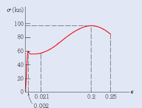
Fig. P11.5
Expert Solution & Answer
Want to see the full answer?
Check out a sample textbook solution
Students have asked these similar questions
Under which of the conditions below is the generalized Hooke’s law applicable for use in analysis?
a. When the material distorts due to any of the normal stresses
b. When the material has a negative value for Poisson’s ratio
c. When the material exceeds its proportional limit but still remains elastic
d. When the material’s cross-section changes along one direction
Which of the following statements is false about the Poisson’s ratio?
a. It is a dimensionless quantity
b. It relates the modulus of elasticity E and the modulus of rigidity G
c. It has a single value for isotropic and homogeneous materials
d. Its magnitude is equal to the negative ratio of the longitudinal strain to the lateral strain.
Stiffness is the property that enables material to withstand high stress without great strain. it is a resistance to any sort of deformation and is a function of the modulus of elasticity, E of the material
True or false
A steel rod is subjected to a gradually applied load (F) which gave a rise to a maximum stress of 200 MPa. The rod is 250 mm long and one part of its length is square and the remainder is circular with a diameter of 25 mm. If the total strain energy in the rod and modulus elasticity of the material is 1.3 J and 200 GPa, determine the following:1.The applied load F2.The total extension of the bar3.The length of the square portion of the bar4.The suddenly applied load that will induce the same amount of energy 5.The load that falls from a height of 8 mm induces 1,3 J in the bar.
Chapter 11 Solutions
Mechanics of Materials, 7th Edition
Ch. 11.3 - Determine the modulus of resilience for each of...Ch. 11.3 - Determine the modulus of resilience for each of...Ch. 11.3 - Determine the modulus of resilience for each of...Ch. 11.3 - Determine the modulus of resilience for each of...Ch. 11.3 - The stress-strain diagram shown has been drawn...Ch. 11.3 - The stress-strain diagram shown has been drawn...Ch. 11.3 - Prob. 7PCh. 11.3 - Prob. 8PCh. 11.3 - Using E = 29 106 psi, determine (a) the strain...Ch. 11.3 - Using E = 200 GPa, determine (a) the strain energy...
Ch. 11.3 - A 30-in. length of aluminum pipe of...Ch. 11.3 - A single 6-mm-diameter steel pin B is used to...Ch. 11.3 - Prob. 13PCh. 11.3 - Prob. 14PCh. 11.3 - The assembly ABC is made of a steel for which E =...Ch. 11.3 - Show by integration that the strain energy of the...Ch. 11.3 - Prob. 17PCh. 11.3 - Prob. 18PCh. 11.3 - Prob. 19PCh. 11.3 - 11.18 through 11.21 In the truss shown, all...Ch. 11.3 - Prob. 21PCh. 11.3 - Each member of the truss shown is made of aluminum...Ch. 11.3 - Each member of the truss shown is made of aluminum...Ch. 11.3 - 11.24 through 11.27 Taking into account only the...Ch. 11.3 - Prob. 25PCh. 11.3 - 11.24 through 11.27 Taking into account only the...Ch. 11.3 - 11.24 through 11.27 Taking into account only the...Ch. 11.3 - Prob. 28PCh. 11.3 - Prob. 29PCh. 11.3 - Prob. 30PCh. 11.3 - 11.30 and 11.31 Using E = 200 GPa, determine the...Ch. 11.3 - Assuming that the prismatic beam AB has a...Ch. 11.3 - Prob. 33PCh. 11.3 - The design specifications for the steel shaft AB...Ch. 11.3 - Show by integration that the strain energy in the...Ch. 11.3 - The state of stress shown occurs in a machine...Ch. 11.3 - Prob. 37PCh. 11.3 - The state of stress shown occurs in a machine...Ch. 11.3 - Prob. 39PCh. 11.3 - Prob. 40PCh. 11.3 - Prob. 41PCh. 11.5 - A 5-kg collar D moves along the uniform rod AB and...Ch. 11.5 - The 18-lb cylindrical block E has a horizontal...Ch. 11.5 - The cylindrical block E has a speed v0 =16 ft/s...Ch. 11.5 - Prob. 45PCh. 11.5 - Prob. 46PCh. 11.5 - The 48-kg collar G is released from rest in the...Ch. 11.5 - Prob. 48PCh. 11.5 - Prob. 49PCh. 11.5 - Prob. 50PCh. 11.5 - Prob. 51PCh. 11.5 - The 2-kg block D is dropped from the position...Ch. 11.5 - The 10-kg block D is dropped from a height h = 450...Ch. 11.5 - Prob. 54PCh. 11.5 - A 160-lb diver jumps from a height of 20 in. onto...Ch. 11.5 - Prob. 56PCh. 11.5 - A block of weight W is dropped from a height h...Ch. 11.5 - 11.58 and 11.59 Using the method of work and...Ch. 11.5 - 11.58 and 11.59 Using the method of work and...Ch. 11.5 - 11.60 and 11.61 Using the method of work and...Ch. 11.5 - 11.60 and 11.61 Using the method of work and...Ch. 11.5 - 11.62 and 11.63 Using the method of work and...Ch. 11.5 - 11.62 and 11.63 Using the method of work and...Ch. 11.5 - Using the method of work and energy, determine the...Ch. 11.5 - Using the method of work and energy, determine the...Ch. 11.5 - The 20-mm diameter steel rod BC is attached to the...Ch. 11.5 - Torques of the same magnitude T are applied to the...Ch. 11.5 - Prob. 68PCh. 11.5 - The 20-mm-diameter steel rod CD is welded to the...Ch. 11.5 - The thin-walled hollow cylindrical member AB has a...Ch. 11.5 - 11.71 and 11.72 Each member of the truss shown has...Ch. 11.5 - 11.71 and 11.72 Each member of the truss shown has...Ch. 11.5 - Each member of the truss shown is made of steel...Ch. 11.5 - Each member of the truss shown is made of steel....Ch. 11.5 - Each member of the truss shown is made of steel...Ch. 11.5 - The steel rod BC has a 24-mm diameter and the...Ch. 11.9 - 11.77 and 11.78 Using the information in Appendix...Ch. 11.9 - 11.77 and 11.78 Using the information in Appendix...Ch. 11.9 - 11.79 through 11.82 For the beam and loading...Ch. 11.9 - 11.79 through 11.82 For the beam and loading...Ch. 11.9 - 11.79 through 11.82 For the beam and loading...Ch. 11.9 - 11.79 through 11.82 For the beam and loading...Ch. 11.9 - 11.83 through 11.85 For the prismatic beam shown,...Ch. 11.9 - 11.83 through 11.85 For the prismatic beam shown,...Ch. 11.9 - 11.83 through 11.85 For the prismatic beam shown,...Ch. 11.9 - 11.86 through 11.88 For the prismatic beam shown,...Ch. 11.9 - 11.86 through 11.88 For the prismatic beam shown,...Ch. 11.9 - 11.86 through 11.88 For the prismatic beam shown,...Ch. 11.9 - For the prismatic beam shown, determine the slope...Ch. 11.9 - For the prismatic beam shown, determine the slope...Ch. 11.9 - For the beam and loading shown, determine the...Ch. 11.9 - For the beam and loading shown, determine the...Ch. 11.9 - 11.93 and 11.94 For the beam and loading shown,...Ch. 11.9 - 11.93 and 11.94 For the beam and loading shown,...Ch. 11.9 - For the beam and loading shown, determine the...Ch. 11.9 - For the beam and loading shown, determine the...Ch. 11.9 - Prob. 97PCh. 11.9 - For the beam and loading shown, determine the...Ch. 11.9 - 11.99 and 11.100 For the truss and loading shown,...Ch. 11.9 - 11.99 and 11.100 For the truss and loading shown,...Ch. 11.9 - 11.101 and 11.102 Each member of the truss shown...Ch. 11.9 - 11.101 and 11.102 Each member of the truss shown...Ch. 11.9 - 11.103 and 11.104 Each member of the truss shown...Ch. 11.9 - 11.103 and 11 104 Each member of the truss shown...Ch. 11.9 - A uniform rod of flexural rigidity EI is bent and...Ch. 11.9 - For the uniform rod and loading shown and using...Ch. 11.9 - For the beam and loading shown and using...Ch. 11.9 - Two rods AB and BC of the same flexural rigidity...Ch. 11.9 - Three rods, each of the same flexural rigidity EI,...Ch. 11.9 - Three rods, each of the same flexural rigidity EI,...Ch. 11.9 - 11.111 through 11.115 Determine the reaction at...Ch. 11.9 - 11.111 through 11.115 Determine the reaction at...Ch. 11.9 - 11.111 through 11.115 Determine the reaction at...Ch. 11.9 - 11.111 through 11.115 Determine the reaction at...Ch. 11.9 - 11.111 through 11.115 Determine the reaction at...Ch. 11.9 - For the uniform beam and loading shown, determine...Ch. 11.9 - 11.117 through 11.120 Three members of the same...Ch. 11.9 - 11.117 through 11.120 Three members of the same...Ch. 11.9 - 11.117 through 11.120 Three members of the same...Ch. 11.9 - 11.117 through 11.120 Three members of the same...Ch. 11.9 - 11.121 and 11.122 Knowing that the eight members...Ch. 11.9 - 11.121 and 11.122 Knowing that the eight members...Ch. 11 - Rod AB is made of a steel for which the yield...Ch. 11 - Each member of the truss shown is made of steel...Ch. 11 - The ship at A has just started to drill for oil on...Ch. 11 - Collar D is released from rest in the position...Ch. 11 - Each member of the truss shown is made of steel...Ch. 11 - A block of weight W is placed in contact with a...Ch. 11 - Two solid steel shafts are connected by the gears...Ch. 11 - A 160-lb diver jumps from a height of 20 in. onto...Ch. 11 - For the prismatic beam shown, determine the slope...Ch. 11 - A disk of radius a has been welded to end B of the...Ch. 11 - A uniform rod of flexural rigidity EI is bent and...Ch. 11 - The steel bar ABC has a square cross section of...
Knowledge Booster


Learn more about
Need a deep-dive on the concept behind this application? Look no further. Learn more about this topic, mechanical-engineering and related others by exploring similar questions and additional content below.Similar questions
- a. Determine whether the new biomaterial follows a most closely a linear elastic, neo-Hookean, or Mooney-Rivlin relationship.b. Show manipulation of strain energy density functions and include comparative plots of data showing results for linear elastic, neo-Hookean, and Mooney-Rivlin relationships.c. list any assumptions givens: . Shear moduli: 11 = U2 = 10MPa. Relationship between elastic constants: E = 2u(1 + v)arrow_forwardNonmetallic-Sheathed Cable (NM) shall be permitted to be derated from the 90 degrees C temperature rating provided the final derated ampacity does not exceed that for ________. A. 50 degrees CB. 60 degrees CC. 75 degrees CD. 90 degrees Carrow_forwardKnowing that the AB pillar shown below is supported at points A andB, determine the greatest load (w) that can be applied to the beam before the column starts tobe buckled or before the steel runs out. Consider leakage voltage = 250 MPa, E=200 GPa, F.S. = 1.5.arrow_forward
- The Poisson’s ratio, μ of common engineering materials lies in the range: 0 1.2 0 0.5 -1 1 - 0.5 0.5arrow_forwardQuestion 4 4. A string has a diameter of 1 cm and the original length of 2 m. The string is pulled by a force of 200 N. Determine the change in length of the string! Young's modulus of the string = 5 x 10⁹ N/m2.arrow_forwardThe load of 2000 lb is to be supported by the two vertical steel wires for which sY = 70 ksi. Originally wire AB is 60 in. long and wire AC is 60.04 in. long. Determine the cross-sectional area of AB if the load is to be shared equally between both wires. Wire AC has a cross-sectional area of 0.02 in2. Est = 29.0(103) ksi.arrow_forward
- The length of the 332332 -in.-diameter steel wire CD has been adjusted so that with no load applied, a gap of 116116 in. exists between the end B of the rigid beam ACB and contact point E. Knowing that E = 29 × 106 psi, determine where a 57-lb (w) block should be placed on the beam in order to cause contact between B and E. For contact, x < in.arrow_forwardThe ratio between normal stress to volumetric strain is known as a. Elastic modulus b. shear modulus c. Rigidity modulus d. Bulk modulusarrow_forwardA bimetallic strip is used as a sensor. The strip has a length of 20 μm. The width of the strip is 1μm. It has an upper layer made of steel (E = 210 x 10 9 N/m 2 ) and the lower layer made of aluminum (E = 80 x 10 9 N/m 2 ). Each layer is 0.1 μm thick. Determine the equivalent stiffness of the strip in the axial direction. Note that the strips are perfectly attached.arrow_forward
- A steel wire of length 1 m and diameter 0.2 mm is elongated by 1 mm due to a weight of 3.14 kg. Determine Young's odulus of steel wire (g=9.8 m/s2)arrow_forwardThe materials laboratory that you direct received the following data on the tensile strength in MPa of 15 samples of Aluminum Nitride. The data obtained for each sample are: Sample Endurance (Mpa) SAMPLE (STRENGTH) MPa 1 190 2 233 3 268 4 160 5 257 6 300 7 310 8 262 9 185 10 205 11 275 12 245 13 220 14 290 15 228 You are asked to calculate the Weibull modulus, m, considering that the probability of failure is n/16, where n is the number of specimens that failed at a given stress. You can use Excel to speed up the calculations.arrow_forwardDetermine the thickness of a 130 mm wide uniform plate for safe continuous operation if the plate is to be subjected to a tensile load that has a maximum value of 260 kN and a minimum value of 110 kN. The properties of the plate material are as follows: Endurance limit stress = 235 MPa, and Yield point stress = 310 MPa. The factor of safety based on yield point may be taken as 1.4.arrow_forward
arrow_back_ios
SEE MORE QUESTIONS
arrow_forward_ios
Recommended textbooks for you
 Elements Of ElectromagneticsMechanical EngineeringISBN:9780190698614Author:Sadiku, Matthew N. O.Publisher:Oxford University Press
 Mechanics of Materials (10th Edition)Mechanical EngineeringISBN:9780134319650Author:Russell C. HibbelerPublisher:PEARSON
 Thermodynamics: An Engineering ApproachMechanical EngineeringISBN:9781259822674Author:Yunus A. Cengel Dr., Michael A. BolesPublisher:McGraw-Hill Education
 Control Systems EngineeringMechanical EngineeringISBN:9781118170519Author:Norman S. NisePublisher:WILEY
 Mechanics of Materials (MindTap Course List)Mechanical EngineeringISBN:9781337093347Author:Barry J. Goodno, James M. GerePublisher:Cengage Learning
 Engineering Mechanics: StaticsMechanical EngineeringISBN:9781118807330Author:James L. Meriam, L. G. Kraige, J. N. BoltonPublisher:WILEY
Elements Of Electromagnetics
Mechanical Engineering
ISBN:9780190698614
Author:Sadiku, Matthew N. O.
Publisher:Oxford University Press
Mechanics of Materials (10th Edition)
Mechanical Engineering
ISBN:9780134319650
Author:Russell C. Hibbeler
Publisher:PEARSON
Thermodynamics: An Engineering Approach
Mechanical Engineering
ISBN:9781259822674
Author:Yunus A. Cengel Dr., Michael A. Boles
Publisher:McGraw-Hill Education
Control Systems Engineering
Mechanical Engineering
ISBN:9781118170519
Author:Norman S. Nise
Publisher:WILEY
Mechanics of Materials (MindTap Course List)
Mechanical Engineering
ISBN:9781337093347
Author:Barry J. Goodno, James M. Gere
Publisher:Cengage Learning
Engineering Mechanics: Statics
Mechanical Engineering
ISBN:9781118807330
Author:James L. Meriam, L. G. Kraige, J. N. Bolton
Publisher:WILEY
An Introduction to Stress and Strain; Author: The Efficient Engineer;https://www.youtube.com/watch?v=aQf6Q8t1FQE;License: Standard YouTube License, CC-BY