(a) The open-loop gain of an amplifier is A = 5 × 10 4 and the closed-loop gain is A f = 50 . (i) What is the feedback transfer function? (ii) What is the ratio of A f to 1 / β ? (b) Repeat part (a) for A = 100 and A f = 20. (Ans. (a) (i) 0.01998, (ii) 0.9990; (b) (i) 0.04, (ii) 0.80 )
(a) The open-loop gain of an amplifier is A = 5 × 10 4 and the closed-loop gain is A f = 50 . (i) What is the feedback transfer function? (ii) What is the ratio of A f to 1 / β ? (b) Repeat part (a) for A = 100 and A f = 20. (Ans. (a) (i) 0.01998, (ii) 0.9990; (b) (i) 0.04, (ii) 0.80 )
(a) The open-loop gain of an amplifier is
A
=
5
×
10
4
and the closed-loop gain is
A
f
=
50
. (i) What is the feedback transfer function? (ii) What is the ratio of
A
f
to
1
/
β
?
(b) Repeat part (a) for
A
=
100
and
A
f
=
20.
(Ans. (a) (i) 0.01998, (ii) 0.9990; (b) (i) 0.04, (ii) 0.80 )
(a)
Expert Solution
To determine
The feedback transfer function for a given closed-loop gain and open-loop gain
The ratio of closed loop gain to 1/β
Answer to Problem 12.1EP
(i) The feedback transfer function is β=0.01998
(ii) The ratio of closed loop gain to 1/β is 0.999
Explanation of Solution
Given Information:
The open-loop gain of a feedback amplifier is A=5×10⁴ and its closed loop gain is Af=50 .
Calculation:
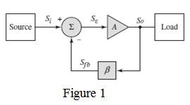
(i) Consider the general feedback amplifier representation in Figure 1. Here, a feedback section with feedback transfer function β is connected to an amplifier having open-loop gain A is connected to form a closed-loop amplifier with gain Af , given by,
Af=A1+Aβ
Substituting the open-loop gain and the closed-loop gain , the feedback transfer function can be obtained as,
β=5×10450−15×104=0.01998
(ii) Substituting the value of β obtained from the previous part, the ratio of closed loop gain to 1/β can be calculated as,
Af1/β=Afβ=50×0.01998=0.999
(b)
Expert Solution
To determine
(i) The feedback transfer function for a given closed-loop gain and open-loop gain
(ii) The ratio of closed loop gain to 1/β
Answer to Problem 12.1EP
(i) The feedback transfer function is β=0.04
(ii) The ratio of closed loop gain to 1/β is 0.08
Explanation of Solution
Given Information:
The open-loop gain of a feedback amplifier is A=100 and its closed loop gain is Af=20 .
Calculation:
(i) Consider the general feedback amplifier representation in Figure 1. Here, a feedback section with feedback transfer function β is connected to an amplifier having open-loop gain A is connected to form a closed-loop amplifier with gain Af , given by,
Af=A1+Aβ
Substituting the open-loop gain and the closed-loop gain , the feedback transfer function can be obtained as,
β=10020−1100=0.04
(ii) Substituting the value of β obtained from the previous part, the ratio of closed loop gain to 1/β can be calculated as,
Af1/β=Afβ=20×0.04=0.8
Want to see more full solutions like this?
Subscribe now to access step-by-step solutions to millions of textbook problems written by subject matter experts!
A unity feedback system with open-loop transfer function given as:?(?) = ??. ?(? + ?)(? + ?)(? + ??)without affecting its operating point (−1.54 ∓ ??2.66) appreciably a- Design a suitable compensator to drive the step response error to zero.b- Design a suitable compensator to reduce step error by factor of 5.
Discuss the difference between the current series negative feedback amplifier and voltage shunt feedback amplifier in terms of output impedance, input impedance, voltage gain, bandwidth, distortion and noise.
Q1/ (a) A negative-feedback amplifier has a closed-loop gain of Af=100 and an open-loop gain of A =5 x 10*. Determine the feedback transfer function p. (b) If p=10.012 and Af = 80, determine the open-loop gain A.
Need a deep-dive on the concept behind this application? Look no further. Learn more about this topic, electrical-engineering and related others by exploring similar questions and additional content below.


 Power System Analysis and Design (MindTap Course ...Electrical EngineeringISBN:9781305632134Author:J. Duncan Glover, Thomas Overbye, Mulukutla S. SarmaPublisher:Cengage Learning