
Introductory Circuit Analysis (13th Edition)
13th Edition
ISBN: 9780133923605
Author: Robert L. Boylestad
Publisher: PEARSON
expand_more
expand_more
format_list_bulleted
Videos
Textbook Question
Chapter 15, Problem 14P
Find the type and impedance in ohms of the series circuit elements that must be in the closed container in Fig. 15.91 for the indicated voltages and currents to exist at the input terminals. (Find the simplest series circuit that will satisfy the indicated conditions.)
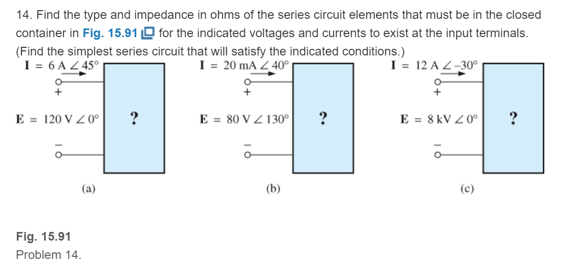
Fig. 15.91
Expert Solution & Answer
Want to see the full answer?
Check out a sample textbook solution
Students have asked these similar questions
q15/
choose the correct answer
In a 200kV transmission system, the transmission line can be used as a medium for power carrier communication.
Select one:
True
False
A simple 60 HZ LT connects two cities, 100 kilometers apart. At the line terminal is connected a 10 MVA load with a power factor of 0.8 across a voltage of 100 kV. The line data is R = 0.1 Ω/Km, L = 2.5 mH/km, C = 0.01 μF/km. Calculate the Sil of the LT.
A transmission line of impedance (0.05 + j0.02) pu interconnects the buses
of a switchyard and a bulk supply point. The receiving end apparent power
is (1.0 + j0.6) pu and sending end voltage, 1/0°pu. Estimate the
i. Sending end apparent power
Chapter 15 Solutions
Introductory Circuit Analysis (13th Edition)
Ch. 15 - For the resistive element in Fig. 15.81: Write the...Ch. 15 - For the resistive element in Fig. 15.82: Write the...Ch. 15 - For the inductive element of Fig. 15.83: a. Write...Ch. 15 - For the inductive element of Fig. 15.84: Calculate...Ch. 15 - For the inductive element of Fig. 15.85: Write the...Ch. 15 - For the capacitive element of Fig. 15.86: Write...Ch. 15 - For the capacitive element of Fig. 15.87:...Ch. 15 - For the capacitive element of Fig. 15.88: Write...Ch. 15 - Sketch the impedance diagram of a 120 k resistor.Ch. 15 - Sketch the impedance diagram of a 5 mH coil...
Ch. 15 - Sketch the impedance diagram of a 0.02 F capacitor...Ch. 15 - Calculate the total impedance of the circuits in...Ch. 15 - Calculate the total impedance of the circuits in...Ch. 15 - Find the type and impedance in ohms of the series...Ch. 15 - For the circuit in Fig. 15.92 Find the total...Ch. 15 - Repeat problem 15 for the circuit in Fig. 15.93,...Ch. 15 - For the circuit in Fig. 15.94: Find the total...Ch. 15 - Repeat Problem 17 for the circuit in Fig. 15.95...Ch. 15 - For the circuit of Fig. 15.96: Find the total...Ch. 15 - For the circuit of Fig. 15.97: Find the current...Ch. 15 - Prob. 21PCh. 15 - Using the oscilloscope reading in Fig. 15.99,...Ch. 15 - Using the DMM current reading and the oscilloscope...Ch. 15 - Using the oscilloscope reading in Fig. 15.101:...Ch. 15 - An electrical load has a power factor of 0.8...Ch. 15 - Find the series element or elements that must be...Ch. 15 - Calculate the voltages V1andV2 for the circuits in...Ch. 15 - Calculate the voltages V1andV2 for the circuits in...Ch. 15 - For the circuit in Fig. 15.105: Determine...Ch. 15 - For the circuit in Fig. 15.106: a. Plot ZT and T...Ch. 15 - Prob. 31PCh. 15 - For the series R-L-C circuit in Fig. 15.108: Plot...Ch. 15 - For the series R-C circuit in Fig. 15.109:...Ch. 15 - For the circuit in Fig. 15.110, determine the...Ch. 15 - For the oscilloscope traces in Fig. 15.111:...Ch. 15 - For the network in Fig. 15.92 (usef=1kHz):...Ch. 15 - For the network in Fig. 15.93: Plot the impedance...Ch. 15 - For the network in Fig. 15.105: Find the rms...
Knowledge Booster


Learn more about
Need a deep-dive on the concept behind this application? Look no further. Learn more about this topic, electrical-engineering and related others by exploring similar questions and additional content below.Similar questions
- 3nu(-n) 0.1nu(-n) + 2nu(-n) Determine if stable system or not using infinite geometric series formulaarrow_forwardUsing nodal analysis, determine the value of voltages at models 1 and 2 in Fig. 15.23.arrow_forwarda) A short transmission line has a sending end voltage of VS and a receiving end voltage of VR. If the receiving end current is IR and the reactance of the line is X, derive an equation for the sending end apparent power. b) based on your answer to a) deduce equations for the active power and reactive powerarrow_forward
- Transmission line with a load Zl = 100 + i80 ohm with characteristic impedance of Z0 = 5 ohm is designed. The transmission line operates at 100 MHz, where is matched with a shunt single- stub tuner. a)Calculate the stub positions. b)Calculate the stub length where open circuit stub is used. c) Calculate the stub length where short circuit stub is used.arrow_forwardKindly do ASAParrow_forward-Asap answer it all tnxarrow_forward
- Determine: re, Zi, Zo, Av(use exact analysis)arrow_forwardFind the Norton's equivalent network at terminals AB of the circuit shown in Fig. 15.55arrow_forwardDetermine the stability of the system whose characteristic equation is 25s^4 + 105s^3 +85s^2+42s + 10 = 0 according to the Routh Stability criterion with the following explanations: a) Create the routh table according to the given characteristic equation. b) Calculate the necessary coefficient in the table you created. c)State whether the system is stable and how you determined it.arrow_forward
- In an autotransformer if the power transferred inductively is equal to the power conducted through, then transformation ratio is given by * 1-0.5 2- 1 3- 2 4- 1.5arrow_forwardA transmission line has generalized circuit constants are A=0.93+j0.016,B=20+j140.The load at the receiving end is 60MVA, 50HZ, 0.8 power factor lagging. The voltage at the supply end is 132KV. Caluclate the load voltage and voltage regulation,Use nominal-π approximation.arrow_forwardThe total capacitance and inductance are C=2x10^(-6) F and L=3x10^(-6) H. The physical length of the line is 900 m. (up to 4 decimal places) >time delay t_d >velocity factor k >velocity of propagation v_p in m/s using the distributed parameters >velocity of propagation v_p in m/s using the relative dielectric constant.arrow_forward
arrow_back_ios
SEE MORE QUESTIONS
arrow_forward_ios
Recommended textbooks for you
 Introductory Circuit Analysis (13th Edition)Electrical EngineeringISBN:9780133923605Author:Robert L. BoylestadPublisher:PEARSON
 Delmar's Standard Textbook Of ElectricityElectrical EngineeringISBN:9781337900348Author:Stephen L. HermanPublisher:Cengage Learning
 Programmable Logic ControllersElectrical EngineeringISBN:9780073373843Author:Frank D. PetruzellaPublisher:McGraw-Hill Education
 Fundamentals of Electric CircuitsElectrical EngineeringISBN:9780078028229Author:Charles K Alexander, Matthew SadikuPublisher:McGraw-Hill Education
 Electric Circuits. (11th Edition)Electrical EngineeringISBN:9780134746968Author:James W. Nilsson, Susan RiedelPublisher:PEARSON
 Engineering ElectromagneticsElectrical EngineeringISBN:9780078028151Author:Hayt, William H. (william Hart), Jr, BUCK, John A.Publisher:Mcgraw-hill Education,
Introductory Circuit Analysis (13th Edition)
Electrical Engineering
ISBN:9780133923605
Author:Robert L. Boylestad
Publisher:PEARSON
Delmar's Standard Textbook Of Electricity
Electrical Engineering
ISBN:9781337900348
Author:Stephen L. Herman
Publisher:Cengage Learning
Programmable Logic Controllers
Electrical Engineering
ISBN:9780073373843
Author:Frank D. Petruzella
Publisher:McGraw-Hill Education
Fundamentals of Electric Circuits
Electrical Engineering
ISBN:9780078028229
Author:Charles K Alexander, Matthew Sadiku
Publisher:McGraw-Hill Education
Electric Circuits. (11th Edition)
Electrical Engineering
ISBN:9780134746968
Author:James W. Nilsson, Susan Riedel
Publisher:PEARSON
Engineering Electromagnetics
Electrical Engineering
ISBN:9780078028151
Author:Hayt, William H. (william Hart), Jr, BUCK, John A.
Publisher:Mcgraw-hill Education,
Resonance Circuits: LC Inductor-Capacitor Resonating Circuits; Author: Physics Videos by Eugene Khutoryansky;https://www.youtube.com/watch?v=Mq-PF1vo9QA;License: Standard YouTube License, CC-BY