
Introductory Circuit Analysis (13th Edition)
13th Edition
ISBN: 9780133923605
Author: Robert L. Boylestad
Publisher: PEARSON
expand_more
expand_more
format_list_bulleted
Concept explainers
Videos
Textbook Question
Chapter 15, Problem 12P
Calculate the total impedance of the circuits in Fig. 15.89. Express your answer in rectangular and polar forms and draw the impedance diagram.
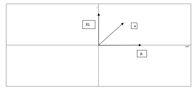
Fig. 18.89
Expert Solution & Answer

Trending nowThis is a popular solution!

Students have asked these similar questions
According to the image answer the following questions.
a) Determine the system function H(z).
b) Plot the zeros and poles of H(z) in the z-plane.
Determine: re, Zi, Zo, Av (use appropriate approximation)
The primary constants of a uniform line 67.19 meters long, have the following values at 171.31 MHz: R = 5215.2491 mΩ / m, L = 1017.7428 nH / m, C = 69.8857 pF / m and G = 43.2532 µS / m. Decide:
a) How much the characteristic impedance and the attenuation coefficient are worth per unit length (in mdB / m) of the same, at said frequency.
Chapter 15 Solutions
Introductory Circuit Analysis (13th Edition)
Ch. 15 - For the resistive element in Fig. 15.81: Write the...Ch. 15 - For the resistive element in Fig. 15.82: Write the...Ch. 15 - For the inductive element of Fig. 15.83: a. Write...Ch. 15 - For the inductive element of Fig. 15.84: Calculate...Ch. 15 - For the inductive element of Fig. 15.85: Write the...Ch. 15 - For the capacitive element of Fig. 15.86: Write...Ch. 15 - For the capacitive element of Fig. 15.87:...Ch. 15 - For the capacitive element of Fig. 15.88: Write...Ch. 15 - Sketch the impedance diagram of a 120 k resistor.Ch. 15 - Sketch the impedance diagram of a 5 mH coil...
Ch. 15 - Sketch the impedance diagram of a 0.02 F capacitor...Ch. 15 - Calculate the total impedance of the circuits in...Ch. 15 - Calculate the total impedance of the circuits in...Ch. 15 - Find the type and impedance in ohms of the series...Ch. 15 - For the circuit in Fig. 15.92 Find the total...Ch. 15 - Repeat problem 15 for the circuit in Fig. 15.93,...Ch. 15 - For the circuit in Fig. 15.94: Find the total...Ch. 15 - Repeat Problem 17 for the circuit in Fig. 15.95...Ch. 15 - For the circuit of Fig. 15.96: Find the total...Ch. 15 - For the circuit of Fig. 15.97: Find the current...Ch. 15 - Prob. 21PCh. 15 - Using the oscilloscope reading in Fig. 15.99,...Ch. 15 - Using the DMM current reading and the oscilloscope...Ch. 15 - Using the oscilloscope reading in Fig. 15.101:...Ch. 15 - An electrical load has a power factor of 0.8...Ch. 15 - Find the series element or elements that must be...Ch. 15 - Calculate the voltages V1andV2 for the circuits in...Ch. 15 - Calculate the voltages V1andV2 for the circuits in...Ch. 15 - For the circuit in Fig. 15.105: Determine...Ch. 15 - For the circuit in Fig. 15.106: a. Plot ZT and T...Ch. 15 - Prob. 31PCh. 15 - For the series R-L-C circuit in Fig. 15.108: Plot...Ch. 15 - For the series R-C circuit in Fig. 15.109:...Ch. 15 - For the circuit in Fig. 15.110, determine the...Ch. 15 - For the oscilloscope traces in Fig. 15.111:...Ch. 15 - For the network in Fig. 15.92 (usef=1kHz):...Ch. 15 - For the network in Fig. 15.93: Plot the impedance...Ch. 15 - For the network in Fig. 15.105: Find the rms...
Additional Engineering Textbook Solutions
Find more solutions based on key concepts
Explain the main function of each of the following major components of a PLC: a. Processor module (CPU) b. I/O ...
Programmable Logic Controllers
Find I0 and I1 in the circuit in Fig.P2.12.
Basic Engineering Circuit Analysis
Does the severity of an electric shock increase ordecrease with eh of the following changes? a. A decrease in t...
Electric Motors and Control Systems
Design an ideal inverting op-amp circuit such that the voltage gain is Av=25 . The maximum current in any resis...
Microelectronics: Circuit Analysis and Design
Three point charges of equal magnitude q, that will yield a zero net electric field at the origin.
Engineering Electromagnetics
With respect to the circuit in Fig. 5.90, (a) employ Thévenin’s theorem to determine the equivalent network see...
Loose Leaf for Engineering Circuit Analysis Format: Loose-leaf
Knowledge Booster


Learn more about
Need a deep-dive on the concept behind this application? Look no further. Learn more about this topic, electrical-engineering and related others by exploring similar questions and additional content below.Similar questions
- If φ(x, y, z) = x 2 z + e y/x , evaluate grad φ at the point (1, 0, −1).arrow_forwardA transmission line has a characteristic impedance of ? = 21.05∠60.4 with propagation constant of 7.561 ? 10-3+ ? 0.002863 . Calculate the primary constants at an angular frequency of 5000 rad/sec.arrow_forwardSolve for Total Powerarrow_forward
- A transmission line has the following primary constants: resistance R = 15 /loop km, inductance L = 3.4 mH/loop km, conductance G = 3µS/km and capacitance C = 10 nF/km. Determine the characteristic impedance of the line when the frequency is 2 kHzarrow_forward5. Given that V0=4|0°V in the circuit below, calculate the magnitude and angle of the Z impedance.arrow_forwardcharacteristic impedance z0 = 50 ohms is a short-circuited coaxial (coaxial) cable with a length d = 0.3λ component is wanted to be made. Use Its frequency is f = 8 GHz. (a) Identify the component. (b) Find the impedance value of the component. (c) Find the parameter value of the component. lesson:electrical and electronical engineeringarrow_forward
- The total capacitance and inductance are C=2x10^(-6) F and L=3x10^(-6) H. The physical length of the line is 900 m. (up to 4 decimal places) >time delay t_d >velocity factor k >velocity of propagation v_p in m/s using the distributed parameters >velocity of propagation v_p in m/s using the relative dielectric constant.arrow_forwarda) A short transmission line has a sending end voltage of VS and a receiving end voltage of VR. If the receiving end current is IR and the reactance of the line is X, derive an equation for the sending end apparent power. b) based on your answer to a) deduce equations for the active power and reactive powerarrow_forwardfind Zi, and rearrow_forward
- Given the following circuit. Determine the Z parameters. * 8Q 10Q “arrow_forwardA transmission line has generalized circuit constants are A=0.93+j0.016,B=20+j140.The load at the receiving end is 60MVA, 50HZ, 0.8 power factor lagging. The voltage at the supply end is 132KV. Caluclate the load voltage and voltage regulation,Use nominal-π approximation.arrow_forwardDetermine: re, Zi, Zo, Av(use exact analysis)arrow_forward
arrow_back_ios
SEE MORE QUESTIONS
arrow_forward_ios
Recommended textbooks for you
 Introductory Circuit Analysis (13th Edition)Electrical EngineeringISBN:9780133923605Author:Robert L. BoylestadPublisher:PEARSON
 Delmar's Standard Textbook Of ElectricityElectrical EngineeringISBN:9781337900348Author:Stephen L. HermanPublisher:Cengage Learning
 Programmable Logic ControllersElectrical EngineeringISBN:9780073373843Author:Frank D. PetruzellaPublisher:McGraw-Hill Education
 Fundamentals of Electric CircuitsElectrical EngineeringISBN:9780078028229Author:Charles K Alexander, Matthew SadikuPublisher:McGraw-Hill Education
 Electric Circuits. (11th Edition)Electrical EngineeringISBN:9780134746968Author:James W. Nilsson, Susan RiedelPublisher:PEARSON
 Engineering ElectromagneticsElectrical EngineeringISBN:9780078028151Author:Hayt, William H. (william Hart), Jr, BUCK, John A.Publisher:Mcgraw-hill Education,
Introductory Circuit Analysis (13th Edition)
Electrical Engineering
ISBN:9780133923605
Author:Robert L. Boylestad
Publisher:PEARSON
Delmar's Standard Textbook Of Electricity
Electrical Engineering
ISBN:9781337900348
Author:Stephen L. Herman
Publisher:Cengage Learning
Programmable Logic Controllers
Electrical Engineering
ISBN:9780073373843
Author:Frank D. Petruzella
Publisher:McGraw-Hill Education
Fundamentals of Electric Circuits
Electrical Engineering
ISBN:9780078028229
Author:Charles K Alexander, Matthew Sadiku
Publisher:McGraw-Hill Education
Electric Circuits. (11th Edition)
Electrical Engineering
ISBN:9780134746968
Author:James W. Nilsson, Susan Riedel
Publisher:PEARSON
Engineering Electromagnetics
Electrical Engineering
ISBN:9780078028151
Author:Hayt, William H. (william Hart), Jr, BUCK, John A.
Publisher:Mcgraw-hill Education,
How do Electric Transmission Lines Work?; Author: Practical Engineering;https://www.youtube.com/watch?v=qjY31x0m3d8;License: Standard Youtube License