
Introductory Circuit Analysis (13th Edition)
13th Edition
ISBN: 9780133923605
Author: Robert L. Boylestad
Publisher: PEARSON
expand_more
expand_more
format_list_bulleted
Videos
Textbook Question
Chapter 15, Problem 27P
Calculate the voltages
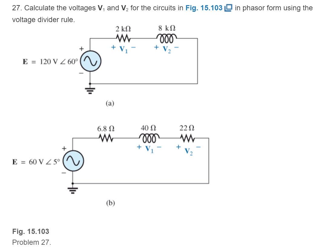
Fig. 15.103
Expert Solution & Answer
Want to see the full answer?
Check out a sample textbook solution
Students have asked these similar questions
SERIES RLC ,TOTAL IMPEDANCE ( NEED NEAT HANDWRITTEN SOLUTION ONLY OTHERWISE DOWNVOTE).
What is the effective impedance of the following network at 10 kHz?
That 680 is Ohms.
Compute the power factor of a two-terminal element with admittance Y = (1/4radical3 - j1/4), S A)1/2 B)radical3 /2 C)radical2 / 2 D)0.25
Chapter 15 Solutions
Introductory Circuit Analysis (13th Edition)
Ch. 15 - For the resistive element in Fig. 15.81: Write the...Ch. 15 - For the resistive element in Fig. 15.82: Write the...Ch. 15 - For the inductive element of Fig. 15.83: a. Write...Ch. 15 - For the inductive element of Fig. 15.84: Calculate...Ch. 15 - For the inductive element of Fig. 15.85: Write the...Ch. 15 - For the capacitive element of Fig. 15.86: Write...Ch. 15 - For the capacitive element of Fig. 15.87:...Ch. 15 - For the capacitive element of Fig. 15.88: Write...Ch. 15 - Sketch the impedance diagram of a 120 k resistor.Ch. 15 - Sketch the impedance diagram of a 5 mH coil...
Ch. 15 - Sketch the impedance diagram of a 0.02 F capacitor...Ch. 15 - Calculate the total impedance of the circuits in...Ch. 15 - Calculate the total impedance of the circuits in...Ch. 15 - Find the type and impedance in ohms of the series...Ch. 15 - For the circuit in Fig. 15.92 Find the total...Ch. 15 - Repeat problem 15 for the circuit in Fig. 15.93,...Ch. 15 - For the circuit in Fig. 15.94: Find the total...Ch. 15 - Repeat Problem 17 for the circuit in Fig. 15.95...Ch. 15 - For the circuit of Fig. 15.96: Find the total...Ch. 15 - For the circuit of Fig. 15.97: Find the current...Ch. 15 - Prob. 21PCh. 15 - Using the oscilloscope reading in Fig. 15.99,...Ch. 15 - Using the DMM current reading and the oscilloscope...Ch. 15 - Using the oscilloscope reading in Fig. 15.101:...Ch. 15 - An electrical load has a power factor of 0.8...Ch. 15 - Find the series element or elements that must be...Ch. 15 - Calculate the voltages V1andV2 for the circuits in...Ch. 15 - Calculate the voltages V1andV2 for the circuits in...Ch. 15 - For the circuit in Fig. 15.105: Determine...Ch. 15 - For the circuit in Fig. 15.106: a. Plot ZT and T...Ch. 15 - Prob. 31PCh. 15 - For the series R-L-C circuit in Fig. 15.108: Plot...Ch. 15 - For the series R-C circuit in Fig. 15.109:...Ch. 15 - For the circuit in Fig. 15.110, determine the...Ch. 15 - For the oscilloscope traces in Fig. 15.111:...Ch. 15 - For the network in Fig. 15.92 (usef=1kHz):...Ch. 15 - For the network in Fig. 15.93: Plot the impedance...Ch. 15 - For the network in Fig. 15.105: Find the rms...
Knowledge Booster


Learn more about
Need a deep-dive on the concept behind this application? Look no further. Learn more about this topic, electrical-engineering and related others by exploring similar questions and additional content below.Similar questions
- A three – branch parallel circuit, with Z1 = 25 ∠ 15° Ω, Z2 = 15 ∠ 60° Ω, and Z3 =15 ∠ 90° Ω, has an applied voltage V = 339.4 ∠ −30° V. Obtain the total apparent power and the overall power factor.arrow_forwardSolve for Total Powerarrow_forwardA simple 60 HZ LT connects two cities, 100 kilometers apart. At the line terminal is connected a 10 MVA load with a power factor of 0.8 across a voltage of 100 kV. The line data is R = 0.1 Ω/Km, L = 2.5 mH/km, C = 0.01 μF/km. Calculate the Sil of the LT.arrow_forward
- 1) X=126, then calculate the equivalent impedance Z.arrow_forwardEvaluate the following: a) 2 / (1+j) ^4 b) j [ (1+j3) / (1-j2) ] ^2arrow_forward5) The power was taken by a C–R series circuit, when connected to a 105V, 2.5 kHz supply, is 0.9kW and the current is 15A. Calculate (a) the resistance, (b) the impedance, (c) the reactance, (d) the capacitance, (e) the power factor, and (f) the phase angle between voltage and current.arrow_forward
- If the reactive factor of the electrical system is 0.4. Compute the power factor of the system. Note: reactive factor (rf) = sin Ø a. 0.4 b. 0.9165 c. 23.58 d. 91.65arrow_forwardA microstrip transmission line is to be used as a capacitor of 4pf at 800MHZ. The PCB dielectric is 3.6. The microstrip dimensions are h= 0.0625in, w= 0.13in, and l=0.002in.What are (a) the characteristic impedance of the line and (b) the reactance of the capacitor.arrow_forwardIn an autotransformer if the power transferred inductively is equal to the power conducted through, then transformation ratio is given by * 1-0.5 2- 1 3- 2 4- 1.5arrow_forward
arrow_back_ios
SEE MORE QUESTIONS
arrow_forward_ios
Recommended textbooks for you
 Introductory Circuit Analysis (13th Edition)Electrical EngineeringISBN:9780133923605Author:Robert L. BoylestadPublisher:PEARSON
 Delmar's Standard Textbook Of ElectricityElectrical EngineeringISBN:9781337900348Author:Stephen L. HermanPublisher:Cengage Learning
 Programmable Logic ControllersElectrical EngineeringISBN:9780073373843Author:Frank D. PetruzellaPublisher:McGraw-Hill Education
 Fundamentals of Electric CircuitsElectrical EngineeringISBN:9780078028229Author:Charles K Alexander, Matthew SadikuPublisher:McGraw-Hill Education
 Electric Circuits. (11th Edition)Electrical EngineeringISBN:9780134746968Author:James W. Nilsson, Susan RiedelPublisher:PEARSON
 Engineering ElectromagneticsElectrical EngineeringISBN:9780078028151Author:Hayt, William H. (william Hart), Jr, BUCK, John A.Publisher:Mcgraw-hill Education,
Introductory Circuit Analysis (13th Edition)
Electrical Engineering
ISBN:9780133923605
Author:Robert L. Boylestad
Publisher:PEARSON
Delmar's Standard Textbook Of Electricity
Electrical Engineering
ISBN:9781337900348
Author:Stephen L. Herman
Publisher:Cengage Learning
Programmable Logic Controllers
Electrical Engineering
ISBN:9780073373843
Author:Frank D. Petruzella
Publisher:McGraw-Hill Education
Fundamentals of Electric Circuits
Electrical Engineering
ISBN:9780078028229
Author:Charles K Alexander, Matthew Sadiku
Publisher:McGraw-Hill Education
Electric Circuits. (11th Edition)
Electrical Engineering
ISBN:9780134746968
Author:James W. Nilsson, Susan Riedel
Publisher:PEARSON
Engineering Electromagnetics
Electrical Engineering
ISBN:9780078028151
Author:Hayt, William H. (william Hart), Jr, BUCK, John A.
Publisher:Mcgraw-hill Education,
Resonance Circuits: LC Inductor-Capacitor Resonating Circuits; Author: Physics Videos by Eugene Khutoryansky;https://www.youtube.com/watch?v=Mq-PF1vo9QA;License: Standard YouTube License, CC-BY