
Introductory Circuit Analysis (13th Edition)
13th Edition
ISBN: 9780133923605
Author: Robert L. Boylestad
Publisher: PEARSON
expand_more
expand_more
format_list_bulleted
Concept explainers
Videos
Textbook Question
Chapter 15, Problem 8P
For the capacitive element of Fig. 15.88:
- Write the voltage and current in phasor form.
- Calculate the impedance of the capacitor
- Find the capacitance of the capacitor.
- Sketch the phasor diagram of the voltage and current.
- Sketch the waveform of the voltage and current.
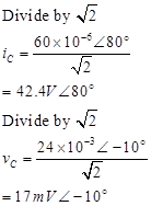
Fig. 15.88
Expert Solution & Answer
Want to see the full answer?
Check out a sample textbook solution
Students have asked these similar questions
For the circuit shown below, determine the voltage of the -j10 2 capacitive reactance. -js 2
1. Choose an ac source voltage with frequency of 60 Hz.2. Choose a value for the following: resistance of a unit of lamp; inductance of a unit of inductor; capacitance of a unit capacitor; impedance of a unit leading power factor load with a power factor between 0.9 and 0.96.3. Let Z1 = impedance of a single lamp; Z2 = impedance of a single practical inductor; Z3 = impedance of a single capacitor; Z4 = impedance of a leading pf load.
Find the ff:
3. A transmission line has a capacitance of 0.1 μF per phase. Determine the inductance of Peterson coilto neutralize the effect of capacitance of (i) complete length of the line, (ii) 97% of the line, (iii) 90%length of the line. The supply frequency is 50 Hz.
[(i) 33.80H (ii) 34.84H (iii) 37.55H]
Chapter 15 Solutions
Introductory Circuit Analysis (13th Edition)
Ch. 15 - For the resistive element in Fig. 15.81: Write the...Ch. 15 - For the resistive element in Fig. 15.82: Write the...Ch. 15 - For the inductive element of Fig. 15.83: a. Write...Ch. 15 - For the inductive element of Fig. 15.84: Calculate...Ch. 15 - For the inductive element of Fig. 15.85: Write the...Ch. 15 - For the capacitive element of Fig. 15.86: Write...Ch. 15 - For the capacitive element of Fig. 15.87:...Ch. 15 - For the capacitive element of Fig. 15.88: Write...Ch. 15 - Sketch the impedance diagram of a 120 k resistor.Ch. 15 - Sketch the impedance diagram of a 5 mH coil...
Ch. 15 - Sketch the impedance diagram of a 0.02 F capacitor...Ch. 15 - Calculate the total impedance of the circuits in...Ch. 15 - Calculate the total impedance of the circuits in...Ch. 15 - Find the type and impedance in ohms of the series...Ch. 15 - For the circuit in Fig. 15.92 Find the total...Ch. 15 - Repeat problem 15 for the circuit in Fig. 15.93,...Ch. 15 - For the circuit in Fig. 15.94: Find the total...Ch. 15 - Repeat Problem 17 for the circuit in Fig. 15.95...Ch. 15 - For the circuit of Fig. 15.96: Find the total...Ch. 15 - For the circuit of Fig. 15.97: Find the current...Ch. 15 - Prob. 21PCh. 15 - Using the oscilloscope reading in Fig. 15.99,...Ch. 15 - Using the DMM current reading and the oscilloscope...Ch. 15 - Using the oscilloscope reading in Fig. 15.101:...Ch. 15 - An electrical load has a power factor of 0.8...Ch. 15 - Find the series element or elements that must be...Ch. 15 - Calculate the voltages V1andV2 for the circuits in...Ch. 15 - Calculate the voltages V1andV2 for the circuits in...Ch. 15 - For the circuit in Fig. 15.105: Determine...Ch. 15 - For the circuit in Fig. 15.106: a. Plot ZT and T...Ch. 15 - Prob. 31PCh. 15 - For the series R-L-C circuit in Fig. 15.108: Plot...Ch. 15 - For the series R-C circuit in Fig. 15.109:...Ch. 15 - For the circuit in Fig. 15.110, determine the...Ch. 15 - For the oscilloscope traces in Fig. 15.111:...Ch. 15 - For the network in Fig. 15.92 (usef=1kHz):...Ch. 15 - For the network in Fig. 15.93: Plot the impedance...Ch. 15 - For the network in Fig. 15.105: Find the rms...
Knowledge Booster


Learn more about
Need a deep-dive on the concept behind this application? Look no further. Learn more about this topic, electrical-engineering and related others by exploring similar questions and additional content below.Similar questions
- The voltage v = 119 sin(100t+50°) V is connected acroos a 8-H inductor. Determine the current in polar form. Write the magnitude only in four decimal places.arrow_forwardFor a driven series RLC circuit, the voltage amplitude V0 and frequency f of the voltage generator are 111 V and 211 Hz, respectively. The circuit has resistance R=415Ω, inductance L=0.312 H, and capacitance C=6.23 μF. Determine the average power Pavg dissipated across the resistor.arrow_forwardsolve for the total complex, apparent, average, and reactive powerarrow_forward
- a)calculate the magnitude of the voltage across the j9 ohm inductor.b) calculate the magnitude of the current through the -j15 ohm capacitor.arrow_forwardWrite a Matlab code to sketch using plot function, y(t)=3 sin(t) for 3 periodsarrow_forwardThe voltage v = 214 sin(100t+50°) V is connected acroos a 215-µF capacitor. Determine the capacitive reactance. Write the magnitude only in four decimal places. the correct answer is 46.5116 please show solution thank you.arrow_forward
- A 50 uF capacitor is connected across a 230V, 50Hz supply. Calculate a) the reactance offered by the capacitor, b) the maximum current, and c) the rms value of the current drawn by the capacitor.arrow_forwardA microstrip transmission line is to be used as a capacitor of 4pf at 800MHZ. The PCB dielectric is 3.6. The microstrip dimensions are h= 0.0625in, w= 0.13in, and l=0.002in.What are (a) the characteristic impedance of the line and (b) the reactance of the capacitor.arrow_forwardA 15 mH inductor is in series with a parallel combination of 80 ohm resistor and 20 microFarad capacitor. If the angular frequency of the applied voltage is1000 rad/sec, find the inductive and capacitive reactance in ohms choices: a. 50, 15 b. 12, 50 c. 14, 49 d. 49, 14arrow_forward
- The voltage v = 207 sin(100t+50°) V is connected acroos a 110-µF capacitor. Determine the instantaneous current at t = 0.004 s. Write the magnitude only in four decimal places.arrow_forwardGiven that: Rc=5.8 kohms Rs=1.8 kohms R1=80 kohms R2=10 kohmsarrow_forwardThe voltage v = 201 sin(100t+50°) V is connected acroos a 110-µF capacitor. Determine the current (RMS) in polar form. Write the magnitude only in four decimal places.arrow_forward
arrow_back_ios
SEE MORE QUESTIONS
arrow_forward_ios
Recommended textbooks for you
 Introductory Circuit Analysis (13th Edition)Electrical EngineeringISBN:9780133923605Author:Robert L. BoylestadPublisher:PEARSON
 Delmar's Standard Textbook Of ElectricityElectrical EngineeringISBN:9781337900348Author:Stephen L. HermanPublisher:Cengage Learning
 Programmable Logic ControllersElectrical EngineeringISBN:9780073373843Author:Frank D. PetruzellaPublisher:McGraw-Hill Education
 Fundamentals of Electric CircuitsElectrical EngineeringISBN:9780078028229Author:Charles K Alexander, Matthew SadikuPublisher:McGraw-Hill Education
 Electric Circuits. (11th Edition)Electrical EngineeringISBN:9780134746968Author:James W. Nilsson, Susan RiedelPublisher:PEARSON
 Engineering ElectromagneticsElectrical EngineeringISBN:9780078028151Author:Hayt, William H. (william Hart), Jr, BUCK, John A.Publisher:Mcgraw-hill Education,
Introductory Circuit Analysis (13th Edition)
Electrical Engineering
ISBN:9780133923605
Author:Robert L. Boylestad
Publisher:PEARSON
Delmar's Standard Textbook Of Electricity
Electrical Engineering
ISBN:9781337900348
Author:Stephen L. Herman
Publisher:Cengage Learning
Programmable Logic Controllers
Electrical Engineering
ISBN:9780073373843
Author:Frank D. Petruzella
Publisher:McGraw-Hill Education
Fundamentals of Electric Circuits
Electrical Engineering
ISBN:9780078028229
Author:Charles K Alexander, Matthew Sadiku
Publisher:McGraw-Hill Education
Electric Circuits. (11th Edition)
Electrical Engineering
ISBN:9780134746968
Author:James W. Nilsson, Susan Riedel
Publisher:PEARSON
Engineering Electromagnetics
Electrical Engineering
ISBN:9780078028151
Author:Hayt, William H. (william Hart), Jr, BUCK, John A.
Publisher:Mcgraw-hill Education,
03 - The Cartesian coordinate system; Author: Technion;https://www.youtube.com/watch?v=hOgKEplCx5E;License: Standard YouTube License, CC-BY