
Introductory Circuit Analysis (13th Edition)
13th Edition
ISBN: 9780133923605
Author: Robert L. Boylestad
Publisher: PEARSON
expand_more
expand_more
format_list_bulleted
Concept explainers
Videos
Textbook Question
Chapter 15, Problem 24P
Using the oscilloscope reading in Fig. 15.101:
- Find the rms value of the current in the series circuit.
- Determine the capacitance C.
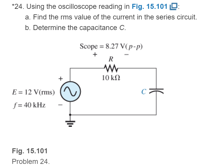
Fig. 15.101
Expert Solution & Answer
Want to see the full answer?
Check out a sample textbook solution
Students have asked these similar questions
solve for the total complex, apparent, average, and reactive power. sketch the power triangle
Given that:
Rc=5.8 kohms
Rs=1.8 kohms
R1=80 kohms
R2=10 kohms
The voltage v = 214 sin(100t+50°) V is connected acroos a 215-µF capacitor. Determine the capacitive reactance. Write the magnitude only in four decimal places.
Chapter 15 Solutions
Introductory Circuit Analysis (13th Edition)
Ch. 15 - For the resistive element in Fig. 15.81: Write the...Ch. 15 - For the resistive element in Fig. 15.82: Write the...Ch. 15 - For the inductive element of Fig. 15.83: a. Write...Ch. 15 - For the inductive element of Fig. 15.84: Calculate...Ch. 15 - For the inductive element of Fig. 15.85: Write the...Ch. 15 - For the capacitive element of Fig. 15.86: Write...Ch. 15 - For the capacitive element of Fig. 15.87:...Ch. 15 - For the capacitive element of Fig. 15.88: Write...Ch. 15 - Sketch the impedance diagram of a 120 k resistor.Ch. 15 - Sketch the impedance diagram of a 5 mH coil...
Ch. 15 - Sketch the impedance diagram of a 0.02 F capacitor...Ch. 15 - Calculate the total impedance of the circuits in...Ch. 15 - Calculate the total impedance of the circuits in...Ch. 15 - Find the type and impedance in ohms of the series...Ch. 15 - For the circuit in Fig. 15.92 Find the total...Ch. 15 - Repeat problem 15 for the circuit in Fig. 15.93,...Ch. 15 - For the circuit in Fig. 15.94: Find the total...Ch. 15 - Repeat Problem 17 for the circuit in Fig. 15.95...Ch. 15 - For the circuit of Fig. 15.96: Find the total...Ch. 15 - For the circuit of Fig. 15.97: Find the current...Ch. 15 - Prob. 21PCh. 15 - Using the oscilloscope reading in Fig. 15.99,...Ch. 15 - Using the DMM current reading and the oscilloscope...Ch. 15 - Using the oscilloscope reading in Fig. 15.101:...Ch. 15 - An electrical load has a power factor of 0.8...Ch. 15 - Find the series element or elements that must be...Ch. 15 - Calculate the voltages V1andV2 for the circuits in...Ch. 15 - Calculate the voltages V1andV2 for the circuits in...Ch. 15 - For the circuit in Fig. 15.105: Determine...Ch. 15 - For the circuit in Fig. 15.106: a. Plot ZT and T...Ch. 15 - Prob. 31PCh. 15 - For the series R-L-C circuit in Fig. 15.108: Plot...Ch. 15 - For the series R-C circuit in Fig. 15.109:...Ch. 15 - For the circuit in Fig. 15.110, determine the...Ch. 15 - For the oscilloscope traces in Fig. 15.111:...Ch. 15 - For the network in Fig. 15.92 (usef=1kHz):...Ch. 15 - For the network in Fig. 15.93: Plot the impedance...Ch. 15 - For the network in Fig. 15.105: Find the rms...
Additional Engineering Textbook Solutions
Find more solutions based on key concepts
A constant voltage of 10V is applied to a 50H inductance, as shown in Figure P3.51 Figure P3 51 The current in ...
Electrical Engineering: Principles & Applications (7th Edition)
Three point charges of equal magnitude q, that will yield a zero net electric field at the origin.
Engineering Electromagnetics
Design an ideal inverting op-amp circuit such that the voltage gain is Av=25 . The maximum current in any resis...
Microelectronics: Circuit Analysis and Design
Explain the main function of each of the following major components of a PLC: a. Processor module (CPU) b. I/O ...
Programmable Logic Controllers
Analog Voltmeter Design Figure P2-98(a) shows a voltmeter circuit consisting of a D'Arsonval meter, two series ...
ANALYSIS+DESIGN OF LINEAR CIRCUITS(LL)
Identify the type of input and output configuration for each diff-amp in Figure 18-35.
Electronics Fundamentals: Circuits, Devices & Applications
Knowledge Booster


Learn more about
Need a deep-dive on the concept behind this application? Look no further. Learn more about this topic, electrical-engineering and related others by exploring similar questions and additional content below.Similar questions
- For the circuit shown below, determine the voltage of the -j10 2 capacitive reactance. -js 2arrow_forwardThe instantaneous power of a parallel RL load is given by 300{1+cos(628.32t+400)} + 400sin(628.32t+400) W. Answer the following (with appropriate units). Real Power: Reactive Power: Apparent Power:arrow_forward1. Choose an ac source voltage with frequency of 60 Hz.2. Choose a value for the following: resistance of a unit of lamp; inductance of a unit of inductor; capacitance of a unit capacitor; impedance of a unit leading power factor load with a power factor between 0.9 and 0.96.3. Let Z1 = impedance of a single lamp; Z2 = impedance of a single practical inductor; Z3 = impedance of a single capacitor; Z4 = impedance of a leading pf load. Find the ff:arrow_forward
- What will be the total admittance of a series combination of a 5 H inductor and 50 ohm resistor? Assume the angular frequency of ac input is 10 rad/s.arrow_forwardThe voltage v = 188 sin(100t+50°) V is connected acroos a 261-µF capacitor. Determine the current at t = 0.008 s. Write the magnitude only in four decimal places.arrow_forwarda)calculate the magnitude of the voltage across the j9 ohm inductor.b) calculate the magnitude of the current through the -j15 ohm capacitor.arrow_forward
- A 50 uF capacitor is connected across a 230V, 50Hz supply. Calculate a) the reactance offered by the capacitor, b) the maximum current, and c) the rms value of the current drawn by the capacitor.arrow_forwardA 30 Ω resistor and a reactor coil (inductor coil) with a 0.2 H inductance and negligible resistance are connected in series across a 120 V, 25 Hz supply. Determine: the impedance of the circuit. the current. the true power in watts taken by the circuit. the power factor. the phase anglearrow_forwardFor a driven series RLC circuit, the voltage amplitude V0 and frequency f of the voltage generator are 111 V and 211 Hz, respectively. The circuit has resistance R=415Ω, inductance L=0.312 H, and capacitance C=6.23 μF. Determine the average power Pavg dissipated across the resistor.arrow_forward
- Identify: a. A 40 μF capacitor is supplied with a 100 V, 60 Hz source. Find the resulting current. b. Three loads are in parallel take the following currents: i1 = 10 sin 314t; i2 = 20 sin (314t -45º); i3 = 30 cos (314t + 30º) A. respectively. Find the RMS value of the resultant current.arrow_forwarda single-stage impluse generator has a 0.01 micro farad capacitor. the wave front and wave tail resistances are 800 ohm and 3000 ohm respectively. if the load capacitor 1200 pico farad , find the front and tail times of the impluse wave produced.arrow_forwardThe voltage v = 119 sin(100t+50°) V is connected acroos a 8-H inductor. Determine the current in polar form. Write the magnitude only in four decimal places.arrow_forward
arrow_back_ios
SEE MORE QUESTIONS
arrow_forward_ios
Recommended textbooks for you
 Introductory Circuit Analysis (13th Edition)Electrical EngineeringISBN:9780133923605Author:Robert L. BoylestadPublisher:PEARSON
 Delmar's Standard Textbook Of ElectricityElectrical EngineeringISBN:9781337900348Author:Stephen L. HermanPublisher:Cengage Learning
 Programmable Logic ControllersElectrical EngineeringISBN:9780073373843Author:Frank D. PetruzellaPublisher:McGraw-Hill Education
 Fundamentals of Electric CircuitsElectrical EngineeringISBN:9780078028229Author:Charles K Alexander, Matthew SadikuPublisher:McGraw-Hill Education
 Electric Circuits. (11th Edition)Electrical EngineeringISBN:9780134746968Author:James W. Nilsson, Susan RiedelPublisher:PEARSON
 Engineering ElectromagneticsElectrical EngineeringISBN:9780078028151Author:Hayt, William H. (william Hart), Jr, BUCK, John A.Publisher:Mcgraw-hill Education,
Introductory Circuit Analysis (13th Edition)
Electrical Engineering
ISBN:9780133923605
Author:Robert L. Boylestad
Publisher:PEARSON
Delmar's Standard Textbook Of Electricity
Electrical Engineering
ISBN:9781337900348
Author:Stephen L. Herman
Publisher:Cengage Learning
Programmable Logic Controllers
Electrical Engineering
ISBN:9780073373843
Author:Frank D. Petruzella
Publisher:McGraw-Hill Education
Fundamentals of Electric Circuits
Electrical Engineering
ISBN:9780078028229
Author:Charles K Alexander, Matthew Sadiku
Publisher:McGraw-Hill Education
Electric Circuits. (11th Edition)
Electrical Engineering
ISBN:9780134746968
Author:James W. Nilsson, Susan Riedel
Publisher:PEARSON
Engineering Electromagnetics
Electrical Engineering
ISBN:9780078028151
Author:Hayt, William H. (william Hart), Jr, BUCK, John A.
Publisher:Mcgraw-hill Education,
What is Filter & Classification of Filters | Four Types of Filters | Electronic Devices & Circuits; Author: SimplyInfo;https://www.youtube.com/watch?v=9x1Sjz-VPSg;License: Standard Youtube License