
Concept explainers
Videos
The uniform wire ABC, of unstretched length 2l, is attached to the supports shown and a vertical load P is applied at the midpoint B. Denoting by A the cross-sectional area of the wire and by E the modulus of elasticity, show that, for δ << l, the deflection at the midpoint B is

Fig. P2.124
To prove the deflection of uniform wire ABC at midpoint B is
Explanation of Solution
Given information:
The unstretched length is
The vertical load is P.
Calculation:
Sketch the uniform wire ABC as shown in Figure 1.
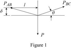
Refer to Figure 1.
The value of
Find the value of vertical load
Substitute for
Find the elongation at point AB using the relation:
Substitute
Sketch the right angle triangle as shown in Figure 2.
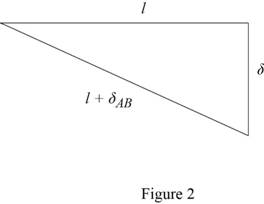
Refer to Figure 2.
Substitute
Hence, the deflection of uniform wire ABC at midpoint B is
Want to see more full solutions like this?
Chapter 2 Solutions
Mechanics of Materials, 7th Edition


- The length of the 332332 -in.-diameter steel wire CD has been adjusted so that with no load applied, a gap of 116116 in. exists between the end B of the rigid beam ACB and contact point E. Knowing that E = 29 × 106 psi, determine where a 57-lb (w) block should be placed on the beam in order to cause contact between B and E. For contact, x < in.arrow_forwardThe truss shown is subjected to forces P = 68 kN, the length L divided equally, and H = 0.6 m. If the resistance of bar 1 is 151 kN; Determine the maximum length (in meters) of the reinforcement so that the resistance of said bar is not exceeded.arrow_forwardThe 70-mm-diameter steel rod ABC, and a brass rod CD of the same diameter, are joined at point C to form the 7.5-m long rod “ABCD”. E’s for the materials in the rod are shown in the picture below. For the loading shown, and neglecting the weight of the rod, determine: a) the deflection of point B b) the deflection of point C c) the deflection of point D d) the longitudinal stress in the middle of section AB e) the longitudinal stress in the middle of section BC f) the longitudinal stress in the middle of section CD a) all elemental stiffness matrices, b) the force matrix, and the c) assembly stiffness matrixarrow_forward
- The 981-kg uniform bar AB is suspended from two cables AC and BD each with cross-sectional area 339 mm2. Find the location x (in mm) of P that can be safely applied to the bar if the stresses in AC and BD are limited to 119 MPa and 52 MPa, respectively. Express your answer in two decimal places.arrow_forwardA 4-ft section of aluminum pipe of cross-sectional area 1.75 in2 rests on a fixed support at A. The 58-in.-diameter steel rod BC hangs from a rigid bar that rests on the top of the pipe at B. Knowing that the smodulus of elasticity is 29 3 106 psi for steel and 10.4 3 106 psi for aluminum, determine the deflection of point C when a 15-kip force is applied at C.arrow_forwardThree bars, two made of aluminum and one made of steel, support a rigid block. An object of weight W is dropped vertically from a distance h above the rigid block. Both steel and aluminum bars have cross-sectional area of 50 mm2 and length of 0.5 m. The elastic moduli for the aluminum and steel are 76 GPa and 184 GPa, respectively. a) If W=1000N and h=0.1m, determine whether the three bars are still safe to perform. b) If h=0.2m, determine the maximum weight that can be dropped without causing failure to the barsarrow_forward
- A rod hanging from a support whose unit mass is 3900 kg/ m3 has a cross-sectional area of 400 mm2 and 250 meters long. If the load of 18 kN is applied at its free end and E = 200 x 103 MPa, determine, a) Elongation due to its ownweight in mm, b) Elongation due to the applied load in mm and c) Total elongation in mm.arrow_forwardThe normal strain in a suspended bar of material of varying cross section due to its own weight is given by the expression γy/3E where γ = 2.9 lb/in.3 is the specific weight of the material, y = 3.4 in. is the distance from the free (i.e., bottom) end of the bar, L = 17 in. is the length of the bar, and E = 24000 ksi is a material constant. Determine, (a) the change in length of the bar due to its own weight. (b) the average normal strain over the length L of the bar. (c) the maximum normal strain in the bar.arrow_forwardThe five-bolt connection shown must support an applied load of P = 330 kN. If the average shear stress in the bolts must be limited to 295 MPa, determine the minimum bolt diameter that may be used in the connection.arrow_forward
- A load P is supported as shown by a steel pin that has been inserted in a short wooden member hanging from the ceiling. The ultimate strength of the wood used is 60 MPa in tension and 7.5 MPa in shear,while the ultimate strength of the steel is 145 MPa in shear. Knowing that b = 40 mm, c = 55 mm, and d = 12 mm, determine the load P if an overall factor of safety of 3.2 is desired.arrow_forwardRigid bar ABC is supported by bronze rod (1) and aluminum rod (2), as shown. A concentrated load P is applied to the free end of aluminum rod (3). Bronze rod (1) has an elastic modulus of E1 = 15,000 ksi and a diameter of d1 = 0.50 in. Aluminum rod (2) has an elastic modulus of E2 = 10,000 ksi and a diameter of d2 = 0.85in. Aluminum rod (3) has a diameter of d3 = 1.00in. The yield strength of the bronze is 48 ksi and the yield strength of the aluminum is 40 ksi. Assume a = 2.5 ft, b = 1.5 ft, L1 = 6 ft, L2 = 8 ft, and L3 = 3 ft. (A) Calculate the cross-sectional areas of the three rods. in in.2 (B) For a factor of safety of 2.1, calculate the allowable stresses in the bronze and the aluminum rods. IN KSI. (C) What is the magnitude of load P that can safely be applied to the structure for a minimum factor of safety of 2.1? in kips (D) The pin used at B has an ultimate shear strength of 58 ksi. If a factor of safety of 2.5 is required, determine the allowable shear stress in this pin.…arrow_forwardBoth portions of the rod ABC are made of an aluminum for which E = 70.4GPa. Knowing that the magnitude of Q is 31876 N, m = 0.35 m, and n = 0.55 m, determine the value of P (in N) so that the deflection at A is zero.arrow_forward
 Elements Of ElectromagneticsMechanical EngineeringISBN:9780190698614Author:Sadiku, Matthew N. O.Publisher:Oxford University Press
 Mechanics of Materials (10th Edition)Mechanical EngineeringISBN:9780134319650Author:Russell C. HibbelerPublisher:PEARSON
 Thermodynamics: An Engineering ApproachMechanical EngineeringISBN:9781259822674Author:Yunus A. Cengel Dr., Michael A. BolesPublisher:McGraw-Hill Education
 Control Systems EngineeringMechanical EngineeringISBN:9781118170519Author:Norman S. NisePublisher:WILEY
 Mechanics of Materials (MindTap Course List)Mechanical EngineeringISBN:9781337093347Author:Barry J. Goodno, James M. GerePublisher:Cengage Learning
 Engineering Mechanics: StaticsMechanical EngineeringISBN:9781118807330Author:James L. Meriam, L. G. Kraige, J. N. BoltonPublisher:WILEY