
Concept explainers
Videos
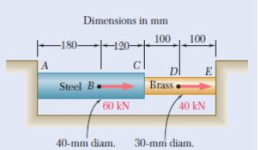
Fig. P2.41
2.41 Two cylindrical rods, one of steel and the other of brass, are joined at C and restrained by rigid supports at A and E. For the loading shown and knowing that Es = 200 GPa and Eb = 105 GPa, determine (a) the reactions at A and E, (b) the deflection of point C.
(a)
Find the reaction at point A and E.
Answer to Problem 41P
The reaction at point A is
The reaction at point E is
Explanation of Solution
Given information:
The length
The length
The length
The length
The young’s modulus for steel
The young’s modulus for steel
Calculation:
Find the area
Here,
Substitute
Find the value of EA for AC section as follows:
Substitute
Find the area
Here,
Substitute
Find the value of EA for CE section as follows:
Substitute
Sketch the free body diagram of cylindrical rod as shown in Figure 1.
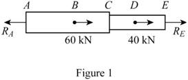
Refer to Figure 1.
Take section A to B.
Find the change in length AB using the relation:
Here, P is the load, L is the length of rod, E is the young’s modulus, and A is the area of the section AB.
Substitute
Take section B to C.
Find the change in length BC using the relation:
Here, A is the area of the section BC.
Substitute
Take section C to D.
Find the change in length CD using the relation:
Here, A is the area of the section CD.
Substitute
Take section D to E.
Find the change in length DE using the relation:
Here, A is the area of the section CD.
Substitute
Take section A to E.
Here,
Substitute
Since the point E cannot move relative to A.
Find the reaction at point A as follows:
Thus, the reaction at point A is
Find the reaction at point E as follows:
Substitute
Thus, the reaction at point E is
(b)
Find the deflection of point C.
Answer to Problem 41P
The deflection of point C is
Explanation of Solution
Calculation:
Determine the deflection of point C using the relation:
Substitute
Substitute
Thus, the deflection of point C is
Want to see more full solutions like this?
Chapter 2 Solutions
Mechanics of Materials, 7th Edition


- Each of the three aluminum bars shown is to be twisted through an angle of 2.1°. Knowing that b = 30 mm, τall = 50 MPa, and G = 27 GPa, determine the shortest allowable length of each bar. Refer to Table 3.1. The shortest allowable length of bar (a) is mm. The shortest allowable length of bar (b) is mm. The shortest allowable length of bar (c) is mm.arrow_forwardBoth portions of the rod ABC are made of an aluminum for which E = 70.4GPa. Knowing that the magnitude of Q is 31876 N, m = 0.35 m, and n = 0.55 m, determine the value of P (in N) so that the deflection at A is zero.arrow_forwardFigure 4 shows two solid cylindrical rods and joined at B. The rod ABC is made of an aluminumfor which E = 70 GPa. Knowing that P = 6 kN and Q = 42 kN, determine the deflection of;a) Point Ab) Point Barrow_forward
- Both portions of the rod ABC are made out of an aluminum forwhich E = 70 GPa. Knowing that the magnitude of P is 4 kN, determine (a)the value of Q so that the deflection at A is zero, (b) the correspondingdeflection of B.arrow_forwardA load P is supported as shown by a steel pin that has been inserted in a short wooden member hanging from the ceiling. The ultimate strength of the wood used is 60 MPa in tension and 7.5 MPa in shear,while the ultimate strength of the steel is 145 MPa in shear. Knowing that b = 40 mm, c = 55 mm, and d = 12 mm, determine the load P if an overall factor of safety of 3.2 is desired.arrow_forwardQ1 / Two solid cylindrical rods are joined at B and loaded as shown. Rod AB is made GPa) and rod BC of brass (E = 105 GPa). Determine (a) the total deformation of the composite rod ABC, (b) the deflection of point B.arrow_forward
- The length of 2 mm diameter steel wire CD has been adjustedso that with no load is applied, a gap of 1.5 mm exists between the end B ofthe rigid beam ACB and a contact point E. Knowing that E = 200 GPa,determine where a 20 kg block should be placed on the beam in order tocause contact between B and E.arrow_forwardThe rod ABC is made of an aluminum for which E = 71.15 GPa. Knowing that P=10.2 kN and Q=51.62kN, determine the deflection (in um) of point B y=0.46 and z=0.56. Round off the final answer in four decimal places.arrow_forwardThe block shown is made of a magnesium alloy for which E = 45 GPa and ν= 0.35. Knowing that σx=–180 MPa, determine (a) the magnitude of σy for which the change in the height of the block will be zero, (b) the corresponding change in the area of the face ABCD, (c) the corresponding change in the volume of the blockarrow_forward
- A steel rod is subjected to a gradually applied load (F) which gave a rise to a maximum stress of 200 MPa. The rod is 250 mm long and one part of its length is square and the remainder is circular with a diameter of 25 mm. If the total strain energy in the rod and modulus elasticity of the material is 1.3 J and 200 GPa, determine the following:1.The applied load F2.The total extension of the bar3.The length of the square portion of the bar4.The suddenly applied load that will induce the same amount of energy 5.The load that falls from a height of 8 mm induces 1,3 J in the bar.arrow_forwardThe truss shown is subjected to forces P = 68 kN, the length L divided equally, and H = 0.6 m. If the resistance of bar 1 is 151 kN; Determine the maximum length (in meters) of the reinforcement so that the resistance of said bar is not exceeded.arrow_forwardA vibration isolation unit consists of two blocks of hard rubber with a modulus of rigidity G= 19 MPa bonded to a plate AB and to rigid supports as shown. Denoting by P the magnitude of the force applied to the plate and by δ the corresponding deflection, determine the effective spring constant, k 5 P/δ, of the system.arrow_forward
 Elements Of ElectromagneticsMechanical EngineeringISBN:9780190698614Author:Sadiku, Matthew N. O.Publisher:Oxford University Press
 Mechanics of Materials (10th Edition)Mechanical EngineeringISBN:9780134319650Author:Russell C. HibbelerPublisher:PEARSON
 Thermodynamics: An Engineering ApproachMechanical EngineeringISBN:9781259822674Author:Yunus A. Cengel Dr., Michael A. BolesPublisher:McGraw-Hill Education
 Control Systems EngineeringMechanical EngineeringISBN:9781118170519Author:Norman S. NisePublisher:WILEY
 Mechanics of Materials (MindTap Course List)Mechanical EngineeringISBN:9781337093347Author:Barry J. Goodno, James M. GerePublisher:Cengage Learning
 Engineering Mechanics: StaticsMechanical EngineeringISBN:9781118807330Author:James L. Meriam, L. G. Kraige, J. N. BoltonPublisher:WILEY