
CONTROL SYSTEMS ENGINEERING
7th Edition
ISBN: 2819770197050
Author: NISE
Publisher: WILEY
expand_more
expand_more
format_list_bulleted
Concept explainers
Videos
Textbook Question
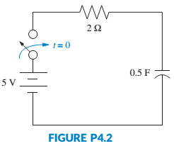
Chapter 4, Problem 4P
Find the capacitor voltage in the network shown in Figure P4.2 if the switch closes at t = 0. Assume zero initial conditions. Also find the time constant, rise time, and settling time for the capacitor voltage.
[Sections: 4.2, 4.3]
Expert Solution & Answer
Want to see the full answer?
Check out a sample textbook solution
Students have asked these similar questions
3m ä+4cx+2kx = 4cj+3ky
For the system given above, obtain the
state-space representation.
26. For the system shown in Figure P4.8, a step torque is
applied at 01 (t). Find
a. The transfer function, G(s) = 02(s)/T(s).
b. The percent overshoot, settling time, and peak
time for 02(t). [Section: 4.6]
T(t) 01(1)
02(1)
ff
1.07 kg-m2
1.53 N-m-s/rad
1.92 N-m/rad
FIGURE P4.8
Q1-for the system shown :
• find the differential equation that relate (T) as output and (Es) as input , take q, = k Eş.
Find time constant.
Get Steady state output at unit step input.
T= room temp ,T1 = surrounding temp , QL= lost heat.
M
Heater
QL
T
T:
Chapter 4 Solutions
CONTROL SYSTEMS ENGINEERING
Ch. 4 - Prob. 1RQCh. 4 - What does the performance specification for a...Ch. 4 - Prob. 3RQCh. 4 - In a system with an input and an output, what...Ch. 4 - Prob. 5RQCh. 4 - Prob. 6RQCh. 4 - 7. What is the difference between the natural...Ch. 4 - Prob. 8RQCh. 4 - Prob. 9RQCh. 4 - Prob. 10RQ
Ch. 4 - List five specifications for a second-order...Ch. 4 - Prob. 12RQCh. 4 - What pole locations characterize (1) the...Ch. 4 - Prob. 14RQCh. 4 - How can you justify pole-zero cancellation?Ch. 4 - Prob. 16RQCh. 4 - 17. What is the relationship between , which...Ch. 4 - Name a major advantage of using time-domain...Ch. 4 - Prob. 19RQCh. 4 - What three pieces of information must be given in...Ch. 4 - 21. How can the poles of a system be found from...Ch. 4 - Prob. 1PCh. 4 - Prob. 2PCh. 4 - MATIAB ML 3. Plot the step responses for Problem 2...Ch. 4 - Find the capacitor voltage in the network shown in...Ch. 4 - For the system shown in Figure P4.3, (a) find an...Ch. 4 - Prob. 8PCh. 4 - MATLAB ML 9. Use MATLAB to find the poles of...Ch. 4 - Find the transfer function and poles of the system...Ch. 4 - MATLAB ML 11. Repeat Problem 10 using MATLAB....Ch. 4 - Write the general form of the capacitor voltage...Ch. 4 - Solve for x(t) in the system shown in Figure P4.5...Ch. 4 - Prob. 15PCh. 4 - Prob. 16PCh. 4 - Calculate the exact response of each system of...Ch. 4 - Prob. 18PCh. 4 - Prob. 19PCh. 4 - For each of the second-order systems that follow,...Ch. 4 - MATLAB ML 21. Repeat Problem 20 using MATLAB. Have...Ch. 4 - GUI Tool GUIT
22. Use MATLAB’s LTI Viewer and...Ch. 4 - Prob. 23PCh. 4 - Find the transfer function of a second-order...Ch. 4 - For the system shown in Figure P4.7, do the...Ch. 4 - For the system shown in Figure P4.8, a step torque...Ch. 4 - Prob. 28PCh. 4 - Prob. 29PCh. 4 - Prob. 30PCh. 4 - Prob. 31PCh. 4 - Prob. 32PCh. 4 - Prob. 33PCh. 4 - Prob. 34PCh. 4 - Prob. 35PCh. 4 - Prob. 36PCh. 4 - State Space SS 38. A system is represented by the...Ch. 4 - Prob. 39PCh. 4 - Prob. 40PCh. 4 - State Space SS 41. Given the following system...Ch. 4 - State Space SS 42. Solve the following state...Ch. 4 - Prob. 43PCh. 4 - Prob. 44PCh. 4 - Prob. 46PCh. 4 - Prob. 47PCh. 4 - Prob. 48PCh. 4 - Prob. 53PCh. 4 - Prob. 54PCh. 4 - A MOEMS (optical MEMS) is a MEMS (Micro...Ch. 4 - Prob. 56PCh. 4 - Prob. 59PCh. 4 - Prob. 60PCh. 4 - Prob. 61PCh. 4 - Prob. 63PCh. 4 - Prob. 67PCh. 4 - Figure P4.l6 shows the step response of an...Ch. 4 - Figure P4. I 7 shows the free-body diagrams for...Ch. 4 - Find an equation that relates 2% settling time to...Ch. 4 - Prob. 74PCh. 4 - Prob. 75PCh. 4 - 76. Find J and K in the rotational system shown in...Ch. 4 - Given the system shown in Figure P4.22, find the...Ch. 4 - Prob. 78PCh. 4 - Find M and K, shown in the system of Figure P4.24,...Ch. 4 - If vi(t) is a step voltage in the network shown in...Ch. 4 - Prob. 81PCh. 4 - Prob. 82PCh. 4 - For the circuit shown in Figure P4.26, find the...Ch. 4 - Prob. 84PCh. 4 - Prob. 86P
Knowledge Booster


Learn more about
Need a deep-dive on the concept behind this application? Look no further. Learn more about this topic, mechanical-engineering and related others by exploring similar questions and additional content below.Similar questions
- 1. For the following mechanical translational system a. Write two differential equations of Order in s domain b. Change to time domain, and choose state variables c. Write the state equations, and the state matrix equation d. Write the output equation if x2 is the output Hint: the state variables will be x1, V1, X2, V2 fv, fit), K3 M K2 M2 0000arrow_forward1. For the following mechanical translational system a. Write two differential equations of Order in s domain b. Change to time domain, and choose state variables c. Write the state equations, and the state matrix equation d. Write the output equation if x2 is the output Hint: the state variables will be x1, V1, X2, V2 X(1) fv, At) KI oll K3 M K2 0000 0000arrow_forwardConsider in Figure 1 = 0. Iff, the translational mechanical system shown P4.17. A 1-pound force, f(t), is applied at 1, find K and M such that the response is characterized by a 4-second settling time and a 1-second peak time. Also, what is the resulting percent overshoot? [Section: 4.6] 1+ 270 Karrow_forward
- Figure 1 shows an electrical system comprising a series RLC circuit and input voltagesource ein(t).(a) Derive the input-output equation with output y = I and input u = ein(t). (b) Using the derived input-output equation, drive the system transfer function G(s)that relates output to input. Use the following numerical values for the electrical systemparameters: resistance R = 2Ω, inductance L = 0.25H, and capacitance C = 0.4F. (c) Using the derived transfer function, derive the time-domain ordinary differentialequation for the input-output equation of this electrical system. (d) Draw the complete block diagram of this series RLC circuit using the derived transferfunction.arrow_forward3. Consider the system shown below. The outputs of the system are the angular displacement of the upper gear (positive about the x-axis) and the Contact force between the upper and lower gear. Assume that the initial conditions for all state variables are zero and that the gears are massless. There are two inputs Ti(t) acting on the top gear and T₂(t) acting on the rightmost disk. If you let • 9₁ denote the state variable for the spring 92 denote the state variable for the rightmost disk. u₁ denote T₁. u₂ denote T₂. You should expect to get the following state space representation and 9= KR + 0₁ 0 LIR -1. 7/2 Ti(t) Jun 0:0⁰ 40² T₂(t) 03 Figure 3: System for problem 3 21 (a) Derive the state-space model (state equation and output equation) in vector form. (b) For the system parameters I = 8 kg m², k = 1 N m,b=2 N s m/rad, R₁ = 1 m, and R₂ = 3 m: i. Use MATLAB to determine the transfer function matrix [G(s)]. ii. What is the ristic equation AS the system? iii. What are the values of the…arrow_forwardQuestion 5: A model for a single joint of a robotic manipulator is shown in Figure below. The usual notation is used. The gear inertia is neglected and the gear reduction ratio is taken as 1:r (Note: r < 1). a) Draw a linear graph for the model, assuming that no external (load) torque is present at the robot arm. b) Using the linear graph derive a state model for this system. The input is the motor magnetic torque Tm and the output is the angular speed o, of the robot arm. What is the order of the system? Jm m (viscous) 1:r Motor Robot Arm Gear Box (Light)arrow_forward
- 4 rad, = 0.5. On the complex plane, draw the root(s) of a 2nd order system with the following characteristics: W₁ = 4 radarrow_forwardb) G₂ (s) = K(s+1)(s+3) (s²-2s+4) In Problem 1(b), find the range/value of K, such that the system has a) poles on the jw-axis; b) poles in the right half-plane; c) poles not on the real-axis.arrow_forward3:17 AM ← Jonathan Wickert, Kemper Lewis - An Introduction to Mechanical Engineering-Cengage L... Figure P8.3 Problem P8.3 The disk in a computer hard drive spins at 7200 rpm (Figure P8.3). At the radius of 30 mm, a stream of data is magnetically written on the disk, and the spacing between data bits is 25 µm. Determine the number of bits per second that pass by the read/write head. 30 mm 7200 rpm BA um 4G+ 49%arrow_forward
- For the system shown in the figure. the system parameters, the length of the rod, l is 2 m, mass of the rigid rod, m is 7, and the stiffness of the springs, k, is the last two digits of 57. Derive the equation of motion, b) Find the transfer function between force input (F) and angular displacement (θ) of the system c) Find the step response of the system, and show time-domain characteristics of the system d) Find the frequency response function, and draw frequency response graphs, and draw bode diagrams, show frequency-domain characteristics.arrow_forward2. Assume a 2 DOF rigid body with a rigid bar, which is supported by a two-spring damper :3k4, m = supports. Inertia and length of the rigid body are I = 10kg and L= 4m. (a) Derive the mathematical model of the system in variable form (b) Write the state space representation of the above system. (c) k₁= k₂ = 800N.m and c₁ = C₂ = 350N.s/m Develop a simulink model and plot all the system response for input y = sin(wt), where w 1 rad = S (d) k₁ 400v, k₂ 800N.m and c₁ = 175N.s/m, c₂ 350N.s/m Develop a simulink model and plot all the system response for input y = sin(wt), where w = = 1 rad 8 - L/4 k₁,c m, I L/4 k₂,c y = sin wtarrow_forward1 / 1 Problem No. 1 1A. 100% + 1B. Consider the translational mechanical system shown in Figure P4.17. A 1-pound force, f(t), is applied at t = 0. If fy = 1, find K and M such that the response is characterized by a 4-second settling time and a 1-second peak time. Also, what is the resulting percent overshoot? [Section: 4.6] 70) 0000 31/1 10000 K FIGURE P4.17 Given the translational mechanical system of Figure P4.17, where K = 1 and f(1) is a unit step. find the values of M and ƒ, to yield a response with 17% overshoot and a settling time of 10 seconds. [Section: 4.6]arrow_forward
arrow_back_ios
SEE MORE QUESTIONS
arrow_forward_ios
Recommended textbooks for you
 Elements Of ElectromagneticsMechanical EngineeringISBN:9780190698614Author:Sadiku, Matthew N. O.Publisher:Oxford University Press
 Mechanics of Materials (10th Edition)Mechanical EngineeringISBN:9780134319650Author:Russell C. HibbelerPublisher:PEARSON
 Thermodynamics: An Engineering ApproachMechanical EngineeringISBN:9781259822674Author:Yunus A. Cengel Dr., Michael A. BolesPublisher:McGraw-Hill Education
 Control Systems EngineeringMechanical EngineeringISBN:9781118170519Author:Norman S. NisePublisher:WILEY
 Mechanics of Materials (MindTap Course List)Mechanical EngineeringISBN:9781337093347Author:Barry J. Goodno, James M. GerePublisher:Cengage Learning
 Engineering Mechanics: StaticsMechanical EngineeringISBN:9781118807330Author:James L. Meriam, L. G. Kraige, J. N. BoltonPublisher:WILEY
Elements Of Electromagnetics
Mechanical Engineering
ISBN:9780190698614
Author:Sadiku, Matthew N. O.
Publisher:Oxford University Press
Mechanics of Materials (10th Edition)
Mechanical Engineering
ISBN:9780134319650
Author:Russell C. Hibbeler
Publisher:PEARSON
Thermodynamics: An Engineering Approach
Mechanical Engineering
ISBN:9781259822674
Author:Yunus A. Cengel Dr., Michael A. Boles
Publisher:McGraw-Hill Education
Control Systems Engineering
Mechanical Engineering
ISBN:9781118170519
Author:Norman S. Nise
Publisher:WILEY
Mechanics of Materials (MindTap Course List)
Mechanical Engineering
ISBN:9781337093347
Author:Barry J. Goodno, James M. Gere
Publisher:Cengage Learning
Engineering Mechanics: Statics
Mechanical Engineering
ISBN:9781118807330
Author:James L. Meriam, L. G. Kraige, J. N. Bolton
Publisher:WILEY
Ch 2 - 2.2.2 Forced Undamped Oscillation; Author: Benjamin Drew;https://www.youtube.com/watch?v=6Tb7Rx-bCWE;License: Standard youtube license